Continue to Site

Welcome to EDAboard.com

Welcome to our site! EDAboard.com is an international Electronics Discussion Forum focused on EDA software, circuits, schematics, books, theory, papers, asic, pld, 8051, DSP, Network, RF, Analog Design, PCB, Service Manuals... and a whole lot more! To participate you need to register. Registration is free. Click here to register now.

Lithium ion battery charger circuit anayoisis

Gaber Mohamed Boraey

Full Member level 2
Joined
Feb 26, 2015
Messages
149
Helped
4
Reputation
10
Reaction score
10
Trophy points
1,298
Activity points
2,249
Hello everyone, hope everybody is ok here
Please I need explain of how this circuit work?, and is it capable for lithium battery charging?, also what the function of the doide connected with green led?
Regards
 

Attachments

  • E565F0AE-C339-4A9E-A2D4-54788BC2757E.jpeg
    E565F0AE-C339-4A9E-A2D4-54788BC2757E.jpeg
    123.5 KB · Views: 126
Hi,

I can only recommend:
* don´t use this circuit. In worst case your Li battery may explode and cause fire.
* educate yourself how Li batteries need to be cahrged ... and about the risks when doing wrong.

There are mayn internet sites and good documents .. just do a search.

A good start could be: https://batteryuniversity.com/

Klaus
 
Okay thanks for the answer, can you explain why the battery will explode?, and is there any modification I can do for fix overcharge issue?
I am just interested in using simple components like zener, resistor and doide and transistor and not IC
Let me know how you can help or other members help
Regards
 
Hi
I am just interested in using simple components like zener, resistor and doide and transistor and not IC
Yes. everybody wants a simple an cheap solution. But sometimes there is no.

Let´s say you want to dive down to the Titanic. You may look for a cheap and simple solution. It it may work .. several times. But you dont have a guarantee...

Same is with Li-Ion charging. So according BatteryUniversity you may charge LiIon up to 4.20V with a tolerance of 50mV.
Simple question: what simple zener circuit do you use just as reference for the 4.20V limit, with the required accuracy over time, temperature and voltage variation?
And this is just one task to solve. There are many other.

If it was that simple ... everybody would use a simple circuit.
But it needs to be accurate, it needs to care about temperature, and current limiting, and minimize wasted power, and needs a time out, and maybe some LEDs to know about the charging state. Reverse battery connection protection, wrong battery detection, worn out battery detection....

Let´s say you use just discrete components. Then
* either it is simnple and not reliable
* or complex .. and still not reliable
* or complex and well designed ... and thus rather complicated.

No one wants to do do all the electronics design just for charging a Li-Ion battry. Thus the semiconductor manufacturer designed dedicated Li-Ion battery charger ICs. with a datasheet explaining all that you need to know to get a reliable charger.

Don´t get me wrong. I dot want to discourage you from tinkering around with electronics. You may use any circuit you like to charge your Li-Ion batteries in your house. But don´t be surprised if they cause fire.

I guess I could design a safe LiIon charger from discrete components with some protection features and some status LEDs. I wouldn´t be surprised if needs 100+ electronic parts. But most hobbyists are not experieinced enough to design a charger with reliable regulation stability (V and I) and do all the worst case heating calculations .. and so on.
****

For sure you may use a more "rugged" battery chemistry. Like Pb or NiCd (don´t know if they still exist). They are way less critical and not known to (easily) explode on overcharging.

Klaus
 
You need to give all your requirements first.
technical related, safety related, production related, cost, regulations, use case...
Simply all.

****

Let's say I want to buy a vehicle.
And all I tell is it should be cheap and reliable.

Klaus
 
Don't want to question the need for a complete specification, but we can probably narrow the selection based on your post #1.
- you want to charge a single cell Li-ion battery from 5V supply, e.g. USB port.
- you obviously need charge current control and end-of-charge switch-off
- charge current to be defined

A simple way to implement the function is a charger IC, see Microchip MCP73812 as an example https://ww1.microchip.com/downloads/en/DeviceDoc/22036b.pdf
--- Updated ---

Or TP4056 as already suggested above.
 
You are right, I overlooked this intention.

In simple words, if you are not targetting to fast charging, a simple constant I/constant U circuit can do. It can be made as discrete circuit, effort depending on the intended voltage accuracy.
 
5V thru an ordinary diode drops the voltage down to the vicinity of a 4V battery. Add a resistosr to limit current. To monitor battery voltage a green led is about right (or combination of diode, red led's, resistor, etc.) With adjustments the led starts out dark then brightens as battery reaches 4.2V.

4V battery charges fm 5V supply thru diode-n-resistor.png
 
V thru an ordinary diode drops the voltage down to the vicinity of a 4V battery. Add a resistosr to limit current. To monitor battery voltage a green led is about right (or combination of diode, red led's, resistor, etc.) With adjustments the led starts out dark then brightens as battery reaches 4.2V.
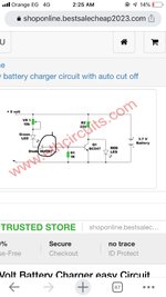
thank you for your care to reply, i think this circuit don't have charge stop, in other word, what will stop charging the battery when it's full charge?, i like the design, but how can be improved for battery charge protection?
 
i think this circuit don't have charge stop, in other word, what will stop charging the battery when it's full charge?

We assume the 5V supply never goes above 5V. Then it takes some finagling to create just the right voltage drop, with a combination of diode junctions and resistors. At 4.2 V the charge current into the battery is down to a negligible level, since a similar level of current exits the battery needed to turn on the green led.

Below is a simpler setup. Adjust potentiometer to deliver 4.2 V maximum. So you have minuscule charge current as the battery approaches 4.2 V.
However it's wasting 50mA through the pot constantly. By installing the diodes (see post #12), you have these benefits:
* diode prevents accidental reverse current flow into your USB port
* green light-emitting diode provides visual cue of battery voltage
* diode drops mean less current is wasted through ohmic resistance.

set 100 ohm pot to max 4_2V (supply is 5V).png
 
Hi,

Usually one builds a charger because one needs a charger.
Usually there is a device ... with a battery. Und thus there are some imortant informations about battery and the according device.
This - and your ideas - tells how the charger should work.

Is it a small or a big battery?
Is the battery disconnected from the circuit during charging, or connected? Does it draw current during charging?
Is it OK if the charging process takes 24 hours or more, or you want it to be charged within 1 hour?
Is it OK if it only charges to 70% of the battery capacity?
We have no idea what you need.

It's like going to the pharmacy and discussing about the side effects of a dedicated cancer drug, while you suffer from a broken leg.

Klaus
 
Is it a small or a big battery?
Is the battery disconnected from the circuit during charging, or connected? Does it draw current during charging?
Is it OK if the charging process takes 24 hours or more, or you want it to be charged within 1 hour?
Is it OK if it only charges to 70% of the battery
It’s small battery, 3.7v li-ion battery, attached photo, no- battery is not disconnected from the circuit during charge, always connected , charging process not ok to take 24hr, can be 1hr enough for full charge , need 100% charge of battery
--- Updated ---

Below is a simpler setup. Adjust potentiometer to deliver 4.2 V maximum. So you have minuscule charge current as the battery approaches 4.2 V.
However it's wasting 50mA through the pot constantly
Is it possible to prevent the current to go to battery when battery is full?
 

Attachments

  • 2A3DAC74-0DDE-448B-836E-4CC7A7B07CF6.png
    2A3DAC74-0DDE-448B-836E-4CC7A7B07CF6.png
    804.9 KB · Views: 46
Last edited:
Is it possible to prevent the current to go to battery when battery is full?
My potentiometer method (post #14) is dirt-simple and lacks safeguards. It's not smart and it's not what you're looking for. It demonstrates how a resistive divider provides 4.2V from a 5V supply. Charging stops automatically when the cell rises to 4.2V. It relies on a crucial feature, namely the regulated voltage remaining stable 5V.

The USB port is convenient for that reason. We expect it provides up to 100mA easily. However it's easy to make a mistake when assembling our homebrew circuit. Because of these risks you have replies in this thread advising to make a smart charger.
 
Hi,

A photo can't replace a datasheet and specifications.
But at least it shows 1.2Ah per battery.
Means if you want to charge three of them in parallel within 1h, then you need more than 3.6A constant charging current.

The batteries will become hot with this hugh current ... especially when almost full. It needs an accurate current and voltage regulation, it needs temperature monitoring, it needs accurate end of charge detection.
Nothing for a cheap unreliable charging circuit.
Don't risk explosion and fire. Use a good dedicated LiIon charger.

Klaus
 
Okay, we just can discuss the solutions here
I not need 3 battery, it’s only one will be used, if current is little it will stay longer time for full charge? , or 70% charge?
 

LaTeX Commands Quick-Menu:

Similar threads

Part and Inventory Search

Welcome to EDABoard.com

Sponsor

Back
Top