Plecto
Full Member level 5
Hello. I have an issue with class AB biasing. I've previously been biasing it using resistors only, but I've been told many times that this is a bad way of biasing because of the risk of thermal runaway. I'm advised to use diodes instead of resistors to prevent this, but using diodes for biasing introduces problems that I can't quite fix. Here's three ways of biasing and my thoughts about them:
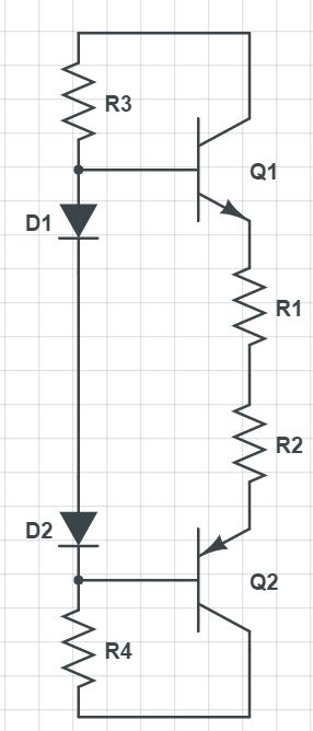
This is the configuration I see most often, but I don't see how this can be done in practice. Assuming equal characteristics of all PN-junctions the biasing current will be ((Vs-1.4)/(R3+R4)*R3)/2*Hfe or half the current flowing through R3 and R4 times the gain. Unless very high bias current is needed, R3 and R4 has to be of some size, but that would severely limit the output voltage as the output voltage is limited by 0.7+IL/Hfe*R3.
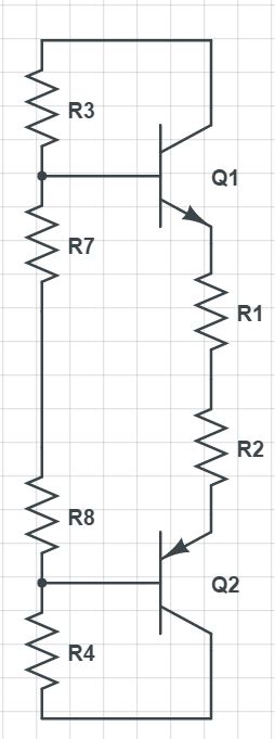
I find this configuration more realistic. The bias current can now be tweaked by adjusting the values of R7 and R8, but the output voltage will still be limited by 1.4+IL/Hfe*R3 so R3 and R4 still have to have pretty low values to preserve the output voltage of the AB stage. An issue with this is that because of the high gain of the darlington pairs the bias current becomes very sensitive to the value of R7 and R8 and after some testing, I could not repeatedly set an accurate bias current. Values that lead to 20mA of bias current on one design does not lead to the same current on another. Another point to make about this circuit is that about half the transistor diode drop resides above R7 and R8 so the bias current will still rise with temperature, although not as much.
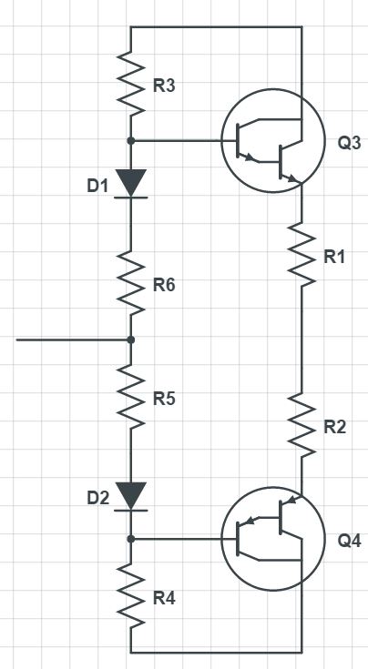
As for this tabu-circuit. The bias current can be accurately and predictably set each time (within 30% or so at least) and the output voltage is not limited by the values of R3 and R4 anymore, but rather the values of R7 and R8 which can be much much smaller without getting an excessive bias current. One issue is of course thermal runaway, but I've made this design many times and never had an issue with it. Dissipating about 20W into a 1.8C/W heat sink will make the bias current rise about 50% due to thermal runaway and then settle in a predictable fashion every single time.
So the question is, what's so wrong about thermal runaway if the increase in bias current can be taken into account? In my experience it has been a very predictable. Am I right to say that the gain vs. temperature graph isn't as steep as the temperature vs. watts cooling graph for heat sinks? Giving that the bias current always settles down I assume that there will always be a point where the cooling of the heat sink get's so big that the thermal runaway stops?
This is the configuration I see most often, but I don't see how this can be done in practice. Assuming equal characteristics of all PN-junctions the biasing current will be ((Vs-1.4)/(R3+R4)*R3)/2*Hfe or half the current flowing through R3 and R4 times the gain. Unless very high bias current is needed, R3 and R4 has to be of some size, but that would severely limit the output voltage as the output voltage is limited by 0.7+IL/Hfe*R3.
I find this configuration more realistic. The bias current can now be tweaked by adjusting the values of R7 and R8, but the output voltage will still be limited by 1.4+IL/Hfe*R3 so R3 and R4 still have to have pretty low values to preserve the output voltage of the AB stage. An issue with this is that because of the high gain of the darlington pairs the bias current becomes very sensitive to the value of R7 and R8 and after some testing, I could not repeatedly set an accurate bias current. Values that lead to 20mA of bias current on one design does not lead to the same current on another. Another point to make about this circuit is that about half the transistor diode drop resides above R7 and R8 so the bias current will still rise with temperature, although not as much.
As for this tabu-circuit. The bias current can be accurately and predictably set each time (within 30% or so at least) and the output voltage is not limited by the values of R3 and R4 anymore, but rather the values of R7 and R8 which can be much much smaller without getting an excessive bias current. One issue is of course thermal runaway, but I've made this design many times and never had an issue with it. Dissipating about 20W into a 1.8C/W heat sink will make the bias current rise about 50% due to thermal runaway and then settle in a predictable fashion every single time.
So the question is, what's so wrong about thermal runaway if the increase in bias current can be taken into account? In my experience it has been a very predictable. Am I right to say that the gain vs. temperature graph isn't as steep as the temperature vs. watts cooling graph for heat sinks? Giving that the bias current always settles down I assume that there will always be a point where the cooling of the heat sink get's so big that the thermal runaway stops?