Continue to Site

Welcome to EDAboard.com

Welcome to our site! EDAboard.com is an international Electronics Discussion Forum focused on EDA software, circuits, schematics, books, theory, papers, asic, pld, 8051, DSP, Network, RF, Analog Design, PCB, Service Manuals... and a whole lot more! To participate you need to register. Registration is free. Click here to register now.

[SOLVED] How to set 6.9v (fully charged) as ref Voltage in voltage monitor (LM358 IC) circuit

Status
Not open for further replies.

speedEC

Full Member level 6
Joined
Apr 1, 2011
Messages
337
Helped
23
Reputation
46
Reaction score
21
Trophy points
1,298
Activity points
4,324
Dear All,

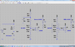
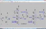
I have made a high/low voltage monitor circuit for my 6v, 4.2Ah lead acid battery using LM358 IC. I have used 3.3v zener - resistor for reference voltage and connected to Inverting Pin. Battery voltage connected to Non-Inverting pin thro' 100K potentiometer. I know that if Voltage at Non-Inverting goes above Inverting Pin, then Output will be High and vice-versa. Also the circuit works. But, I don't know whether it shows correctly or have I not fully understand the concept. Bcoz, If I set reference voltage using 3.3v zener, it always stays constant at 3.3v even if there is any changes in voltage. If so, if the battery voltage is above 3.3v, the LED will be lit for HIGH Voltage. Also, If I goes down below 3.3v, The low voltage LED lit. Is this correct? How can I set 6.9v as HIGH VOLTAGE and 5.5v as LOW VOLTAGE? I am very much confused.

Urgent help pl.

thanks
pmk
 

I think you need a Window Comparator Circuit. You can set high and low limits using a resistor divider circuit.
Just google 'Window Comparator Circuit' and you should get some results.
 

Thanks btbass for your suggestion. My circuit works fine. But, what I want to know is how to set High Voltage and Low voltage. As you suggested, I have google and check the window comparator circuit. It looks same. Can you pl help me?

thanks
pmk
 

    V

    Points: 2
    Helpful Answer Positive Rating
You need to post your circuit diagram so we can see what you've got.
 

If you have a draft circuit (better with the actual values), it helps a lot to complete the idea, perhaps without the need to make a different circuit.
 

    V

    Points: 2
    Helpful Answer Positive Rating
Thanks to both of you KerimF and btbass for your response. Sorry for delayed reply. Last 2 days I could not able to access internet bcoz of Internet Connection problem. Today only everything corrected. Ok. As you said, I posted the circuit of High/Low Voltage monitoring using LM358 IC. pl help.

View attachment VoltageMonitor_LM358.bmp

Pl Note: GREEN LED for High Voltage indicator and RED LED for Low Voltage indicator.

thanks,
pmk
 

If you have a draft circuit (better with the actual values), it helps a lot to complete the idea, perhaps without the need to make a different circuit.

Yes. It is 100% correct what you said KerimF. Bcoz, I have confused only on Potentiometer. If I use voltage divider (exact resistor values as you said) instead of POT, I can able to understand and complete the project even now. For example, If I use voltage divider to give 3.3v to Non-Inverting (+) Pin on LM358 to compare with Inverting Input (-) pin [that set at 3.3v using zener] when battery reaches 6.9v. If I use R1 as 10K and R2 as 9.3K (using two 4k7 in series), I can get 3.34v when Battery reaches 6.9v. Can I use this instead of POT?

Pl see the Picture :

View attachment edaboard_VoltDivider_New.bmp

View attachment edaboard_VoltDivider.bmp

thanks
pmk
 
Last edited:

I got your idea... I try to study your circuit in details and I will likely draw a similar one too.

Added:
I noticed, though this is not too important, that with R6=100R, the zener current is about 27mA @6V. Obviously it can be lowered to 5mA in worst case. That is to let H_zener= 5mA at 5V which is below the limit 5.5V). In this case:
R6 = (5V-3.3) / 5mA = 340E
R6 = 390 as a standard value
By the way:
@6.9V, I_zener = (7-3.3) / .39 = 9.5 mA (it may be a little lower since V_zener will be higher a little bit.
I like to point out that perhaps you intentionally increased the zener current to minimize the change of its voltage between 5.5V and 6.9V of the battery.
But since, in any case, it is hard to find standard resistors (E12) to match exactly the zener voltage at 5.5V and 6.9V, the dividers can still be realized even if the V_zener changes a few hundreds of mV.

Added:
I assume @6.9 the battery is under charge. If the charging current is relatively high, there would be a voltage ripple at its positive terminal (mainly if your testing node is closer to the charger output. Perhaps it will be a good idea to add a capacitor to smooth this ripple at least to the 6.9V divider.

Kerim
 
Last edited:

You did well... but we cannot be sure 100% what would be the exact voltage of the 3.3 zener at 5.5V and 6.9V
The solution is to use a 5K pot with two resistors (one at each side) for fine tuning.
 

In order to zener work on 6.9v and 5.5v, we can supply sufficient current to zener at both voltages. So, If we select proper resistor we can get correct result. Am I correct? This will eliminate the use of POT.

thanks
pmk

---------- Post added at 22:40 ---------- Previous post was at 22:38 ----------

You mean to use POT with resistor instead of Zener for Vref (Inverting Input)?

thanks
pmk
 

You mean to use POT with resistor instead of Zener for Vref (Inverting Input)?

We cannot let all sensed voltages as variables (referenced to the variable V_bat). One of the three should be fixed and I think the ref voltage is the best choice.
So what I meant is to use a POT and two resistors for each opamp to detect low or high. The POT will hep to make the final fine tuning and let the LEDs turn on too close to 6.9V and 5.5V. You know a real circuit is not always as we like it to be :) mainly if we don't try to use costly components.

I am drawing the circuit :)
 

I am waiting for the circuit.

thanks
pmk
 

Hope I didn't miss something.
 

Attachments

  • batt_hi_lo_01.png
    batt_hi_lo_01.png
    107 KB · Views: 102

If You don't mind, I have a clarification on this circuit.

1. POT Connected to Inverting Input as Vref (-) and Zener Resistor combination connected to Non-Inverting Input (+) for HIGH VOLTAGE MONITOR. Is this correct?

thanks
pmk
 

You are always welcome. I am not perfect :)

When I drive LEDs, most opamps (which I have) sink current at their ouput better than sourcing it. So I used to connect the LED anode to Vcc as I did for both opamps in the circuit.
Now when IN- of U1 becomes higher than Vref, the ouput goes low and the LED is turned on. OK?

Edited:
If anything seems illogical or not well... please don't hesitate to point it out.

Added:
On your schematic, the LED at the output of U1 (for high) is reversed so it will be turned on if the output is high. This let you be confused why I changed the polarity at the input (because I changed the polarity of the LED at the output)
 
Last edited:

Ok. I Understand now. But 2 more clarifications please. The Value of (R11, R12 and R13) AND (R21 and R23)? Bcoz, Voltage using Voltage divider thro' resistors (R21 and R23) will be around 2.76v. Will the POT gives additional voltage? If I raise any silly question pl forgive me.

thanks
pmk
 

You are right, the POT gives additional voltage, let us see how to calculate the minimum and maximum voltages that we can get by varying the position of the POT tap (behind U2):
Vmin = Vbat * R23 / (R21+Rp21+Rp22+R23) = Vbat * 33 / (22+2.5+2.5+33) = Vbat * 0.55
Vmax = Vbat * (Rp21+Rp22+R23 / (R21+Rp21+Rp22+R23) = Vbat * (2.5+2.5+33) / (22+2.5+2.5+33) = Vbat * 0.633
So if Vbat = 5.5 CORRECTED (it was 6.9)
Vmin = 3.025 V
Vmax = 3.483 V

Please note that Rp21+Rp22 = 5K
so if we set Rp22 = x , Rp21 = 5-x

For U2:
V (pot) = Vbat * (x+33) / 60
Vmin is when x=0
Vmax is when x=5

Similarly for U1
V (pot) = Vbat * (x+33) / 72
Vmin is when x=0 => Vmin = 33/72 = 3.16 V
Vmax is when x=5 => Vmax = (5+33)/72 = 3.64 V
 
Last edited:
Ok fine. Really hats-off to you. Hope my project has been almost completed. Great thanks to you and all. Bye.

thanks
pmk
 

Since you have 5V regulated, you may take advantage of it and replace Rz and Dz (the zener) with a voltage divider that gives 2.5 V for example (by using two equal resistors). But the values of the other resistors at the IN of the opamp should be recalculated... if you like we can do it.

Added:
Below is a modified version in case you will like to use the regulated 5V
 

Attachments

  • batt_hi_lo_02.png
    batt_hi_lo_02.png
    111.6 KB · Views: 105
Last edited:

Status
Not open for further replies.

Part and Inventory Search

Welcome to EDABoard.com

Sponsor

Back
Top