Continue to Site

Welcome to EDAboard.com

Welcome to our site! EDAboard.com is an international Electronics Discussion Forum focused on EDA software, circuits, schematics, books, theory, papers, asic, pld, 8051, DSP, Network, RF, Analog Design, PCB, Service Manuals... and a whole lot more! To participate you need to register. Registration is free. Click here to register now.

Connecting uart tx with RF circuit

Status
Not open for further replies.

mamech

Full Member level 3
Joined
Nov 9, 2010
Messages
176
Helped
0
Reputation
0
Reaction score
0
Trophy points
1,296
Activity points
3,135
Hello Everyone

I am not sure that I am posting in the right place, but here is my question:

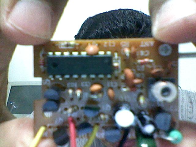
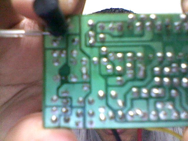
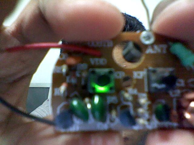
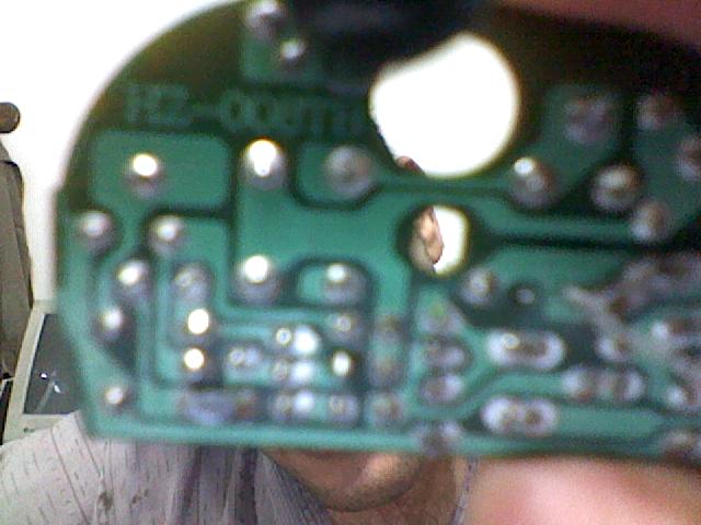
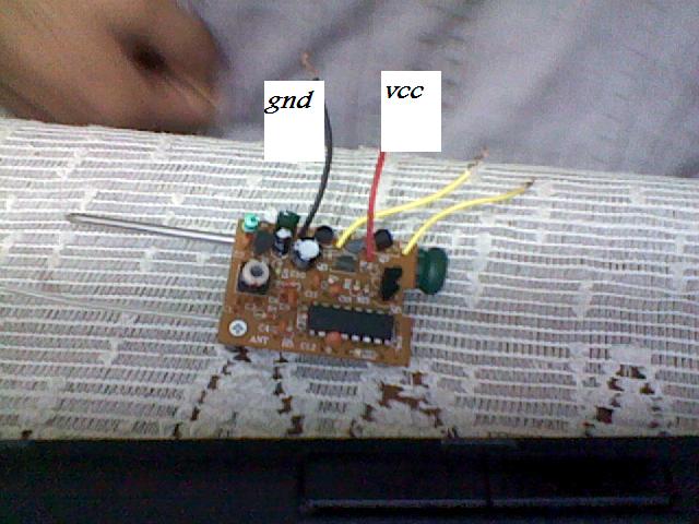
I have an RF transmitter and an RF receiver which I got them from old cheap kids toy, I thought that I can use them to connect tx of a micro to rx of another one wireless. I have a very limited knowledge about RF and wireless circuits, but I was having some doubts that both of RF transmitter and the receiver are not designed for the purpose I want. When I gave it a try, nothing worked as I supposed. I was working on baudrate of 9600, but I thought that if I lowered the baudrate greatly, this could solve the problem. I reached with the baudrate even to 19, but nothing worked !! When the micro starts to send by tx, the RF receiver goes high and I read voltage on its output (which means it does receive the signal), but the micro does not understand it. I tried to put a 33pf capacitor parallel with rx receiver to filter the signal, but nothing worked.

I know that may be the manufacturing company of the toy made some sort of low pass filters, so only low frequencies pass, but I think baud rate of 19 is already a very low one.


Can anyone help me????
 

Do you have the model numbers of the TX/RX pair? To achieve 9600 BAUD you'll need to using an encoding/decoding scheme like Manchester. Without an encoding scheme you'll probably top out at 1200 BAUD.

Checkout the new formed group:

**broken link removed**

I have dozens of links already posted many concerning the RF/SubGHz TX/RX pairs. If you don't find some post in the group, PM me and let me know what you need to get you started.

If you join the group, start a new thread explaining what you have as far as the TX/RX pairs, it will remind me as well as others to look for relevant info for your project.
 
Last edited by a moderator:

Do you have the model numbers of the TX/RX pair?

I did not buy the modules, I got them from a low cost kids toy (I broke the toy to get the tx rx pair form it), but I found written on the back of the transmitter "HZ-008TB", and on the back of the receiver "HZ-008RB".
I searched the net to see what those numbers stands for, but I found nothing.

To achieve 9600 BAUD you'll need to using an encoding/decoding scheme like Manchester. Without an encoding scheme you'll probably top out at 1200 BAUD.

So I suppose that it should work even without Manchester if I lowered the baud rate under 1200. I did that already(I tried very low baud rates), but it did not work.

I attach with this message photos for the modules. I know that is silly, because the photos are not clear and do not show or describe anything.

Thank you very much


I think its a 27MHz pair, ones i had seen in a toy remote car.
From where did u taken the demodulated data (in Rx) ?
If u could draw the circuit diagram of receiver then i think experts here could help U. More over, i think u have to make it sure the connection u had taken from the receiver is the exact demodulated o/p.
 

What are the markings on the IC?

It's hard to tell by the photos, very blurry, what the pair may actually be.

You can pickup a 315/434 MHz Pair for just a few dollars if you want to experiment with RF/SubMHz data transmission.
 

I think its a 27MHz pair, ones i had seen in a toy remote car.
Yes exactly, I got it from remote controlled car.

From where did u taken the demodulated data (in Rx) ?


I measured voltage on the 2 yellow wires while I was pressing button on transmitter, and I found that one of them go high when I press the button, so I concluded that the one that goes high can be used to get the data by it. The other yellow wire seems to be ground. Those 2 yellow wires in receiver were as I remember connected to small dc motor
in the car, while the red and black was connected to the battery.

If u could draw the circuit diagram of receiver then i think experts here could help U.

I hope that I could do this, the circuit is small and stuffed with components, and some of these components even I do not know what it can be. I think if this is the only solution to solve this problem, then I will be forced to do so, but I this schematic will have missing values of ceramic disk capacitors and coils etc., will this be helpful schematic with these values missing??

More over, i think u have to make it sure the connection u had taken from the receiver is the exact demodulated o/p.

I think this is not the case because the receiver has only 4 wires (the above mentioned wires), so they are not a lot, or do you think that there is certain point that I should take the output from ?

Thank you very much

---------- Post added at 22:07 ---------- Previous post was at 21:56 ----------

What are the markings on the IC?

Written on it: TXM (middle left) RX-3 (upper right) ZYX0803 (bottom right)

It's hard to tell by the photos, very blurry, what the pair may actually be.

I know that, sorry but the photo is taken by my webcam.
You can pickup a 315/434 MHz Pair for just a few dollars if you want to experiment with RF/SubMHz data transmission.
The problem that this piece is available in my country with a price (in national cuurency) multipled by five of the price in dollars (due to the difference of currencies). I have seen rxtx pair over the net with about 15 USD, I can buy it here with about 85 L.E

I was so pleased when the idea of using this part of toy instead of buying the module came to my mind, as I will save some money. I thought that things are so straight forward. I really do not understand where the problem is. I tested the rx tx pairs with a led, and I ensured that they are working fine, but why they can not deliver data correctly?!!

Thanks for help
 

An LED glowing while pressing a button on remote doesn't mean it is the data out.You could not take the yellow wire as data out because it is the wire to be connected to the motor(as u told). While pressing the remote keys(up/down, left/right) actually u are sending 4 different serial data (modulated with the carrier) to the receiver. There will be a transistor and few coils and caps to detect the particular modulated signal. Then the IC which u r seeing in the receiver may be the serial data decoder which decodes the serial data and activates the corresponding motor control pins. And this motor control o/p from the IC will be connected to some other motor driving ICs or transistor pairs. So the decoder O/P will not contain the serial data, instead it will be always HIGH while remote button is pressed. And also, it may not become LOW instantly after releasing the remote button.(those delays are all decided by the decoder IC).
So as an experiment, what u can do is, u can try to find the message signal o/p of transmitter serial data generator chip and u can replace it with the Tx signal of uC. Then what u want to do is , u need to find the demodulated o/p of the RF section of the receiver. If the demodulation is done by external components then this demodulated O/P will be connected to the data in of the decoder IC(if that IC is exactly the decoder) . Now if the demodulation is performed inside the IC, then its hard to get the demodulated O/P.

So at least, if u get the datasheet of the IC pair then it will be easy.
OR u should some how draw the circuit and post it here so that many analog circuit designers and experts in this forum could help U.
 

Actually the RX-3 is a fairly common CMOS LSIs designed for remote controlled car applications.

The RX3 has only 2 keys with 3 states, i.e. forward key for forward function, backward key for backward function, and stop function if there is no signal.


Datasheet:

**broken link removed**


It maybe a challenge to use this configuration for data.
 
Maybe by analogy to the way pulsed IR is used, mamech could pulse the encoder frequencies (forward = 1KHz; reverse = 250 Hz) and use the detected pulse widths at the forward (pin 11) or reverse pin (pin 8 ) for two channels of data. In a very simplistic application, for example, a pulse width of 1 mS would be a "0" and 2 mS would be a "1". A more practical approach would be to use Manchester or other similar-purpose encoding.

As an alternative, pin 11 pulses would be "1" and pin 8 pulses would be "0."

Here's a link to the Embedded Wireless Network group's list on Manchester encoding/decoding:

John
 
Last edited:
Hi John,

Well that is certainly a novel idea and doable.

However, with frequencies of 1K/250 Hz it's going to be a painfully slow baud rate.

Send your commands and grab a cup of coffee slow!

---------- Post added 29-05-11 at 00:23 ---------- Previous post was 28-05-11 at 23:16 ----------

... I thought that I can use them to connect tx of a micro to rx of another one wireless. I have a very limited knowledge about RF and wireless circuits, but I was having some doubts that both of RF transmitter and the receiver are not designed for the purpose I want. When I gave it a try, nothing worked as I supposed. I was working on baudrate of 9600, but I thought that if I lowered the baudrate greatly, this could solve the problem. I reached with the baudrate even to 19, but nothing worked !! When the micro starts to send by tx, the RF receiver goes high and I read voltage on its output (which means it does receive the signal), but the micro does not understand it. I tried to put a 33pf capacitor parallel with rx receiver to filter the signal, but nothing worked.

What did you use to test the RF connection, PC, MCU, etc? And exactly how did you make the connection?
 

OR u should some how draw the circuit and post it here so that many analog circuit designers and experts in this forum could help U.
I think the receiver circuit is similar to what exists in ic datasheet

---------- Post added at 15:59 ---------- Previous post was at 15:06 ----------

Maybe by analogy to the way pulsed IR is used, mamech could pulse the encoder frequencies (forward = 1KHz; reverse = 250 Hz) and use the detected pulse widths at the forward (pin 11) or reverse pin (pin 8 ) for two channels of data. In a very simplistic application, for example, a pulse width of 1 mS would be a "0" and 2 mS would be a "1". A more practical approach would be to use Manchester or other similar-purpose encoding.

As an alternative, pin 11 pulses would be "1" and pin 8 pulses would be "0."

Here's a link to the Embedded Wireless Network group's list on Manchester encoding/decoding:

John

Thank you very much for you ideas.

I have some questions:

1-I understand from your previous post that sending UART directly is not possible in this situation, but I should use Manchester. Have I understood you right?

2-There is a library for Manchester code in MikroC (the complier that I work with), but I found that there is a note in the library:
"Note : Baud rate used is 500 bps. " So does this mean that I cannot use it in this application , because the baudrate must be either 1000 or 250?

3-If used Manchester coding, should I get the output from receiver from 11 or 8 ?


Thanks very much

---------- Post added at 16:20 ---------- Previous post was at 15:59 ----------

Hi John,

Well that is certainly a novel idea and doable.

However, with frequencies of 1K/250 Hz it's going to be a painfully slow baud rate.

Send your commands and grab a cup of coffee slow!

I just want to send 2 float numbers, to another micro in some control application. I hope that the delay does not make the control action come too late.
What did you use to test the RF connection, PC, MCU, etc? And exactly how did you make the connection?

I used MCU. I programmed it to turn on a led if it receives certain character from rx, and I made tx in the same micro to send this character.

For the connection: In the transmitter side, there is to buttons for fw and bw. I soldered a wire in the back of the fw button(I think it is fw button), so this wire is connected directly after the fw button. for the receiver side I just took the one of the yellow wires(that produces the o/p signal) and connected it with the micro.

I made some other tries with a terminal program on a pc, but this time I took the ouput from 8 or 11, but I got nothing on the terminal program.The receiver sends rubbish data without I send any thing.
 

But now what i understood from ur post is,
U r controlling the forward control button using the Tx SIGNAL of a uC. Right?
So u are switching the forward button in according to the Tx signal level.
But i think this is not a good method for sending high speed data because if u press forward button then it will take some delay (a few cycles of 1KHz) for the IC to confirm the 1KHz signal signal is received. And also, in some remote cars, i observed that the car motor supply (in ur case yellow wire) will not become low instantly when u release the forward button.

Now what i am thinking is, u can try to give ur Tx signal to be modulated with the carrier instead of the 1khz & 250khz square wave from transmitter IC. And in receiver instead of getting the 1khz or 250Hz signal , u 'may' get the Tx data signal.
 

I have some questions:

1-I understand from your previous post that sending UART directly is not possible in this situation, but I should use Manchester. Have I understood you right?

Yes, I think Manchester or similar coding that looks at the transitions rather than actual pulse widths will be the most reliable. In your case, you will be looking at one of the pins (forward or reverse) and monitoring its transitions. Let's consider only pin 11 (forward). I don't recall that the datasheet said how many of the 1 KHZ oscillations must be received before changing that pin's state. I suspect it looks for a short period and then changes state. You will need to determine that, as it will affect your maximum baud rate. Do you have an oscilloscope available? If not, here is an approach I would try to get a very rough estimate:

1) Set-up a 555 or similar oscillator at 1 KHZ and gate that oscillator with another 555 at a lower frequency. This bypasses the transmitter, but you could also consider using the lower frequency oscillator to pulse the forward switch on the transmitter. I suggest a duty cycle of 10 to 20% for the gating pulse (see below), but a duty cycle near 50% should also work.
2) Use an LED on pin 11 to tell when it goes high.
3) Adjust the frequency of the gating oscillator to between 10 and 100 HZ.
4) The highest frequency at which you first see the LED flicker will give you some idea of the minimum number of pulses the receiver must see before changing state. Don't forget the duty cycle affects the number of pulses sent.
5) You can use that information to figure out your maximum baud.

Obviously, this is just a thought experiment. I have not done it. Let's say, for example, that you notice flicker at 50 Hz, 20% duty cycle. 50 Hz is 20 mS between pulses. 20% of that would be a 4 mS pulse of 1 KHz or 4 oscillations. I suspect it will require more than that to cause a state change. The shorter duty cycle is used to accentuate off time and possible make it easier to notice flicker. Also, if you observe from the corner of your eye (peripheral vision), you will more readily detect flicker. There are lots of assumptions here (e.g., are the minimum off and on periods for a state change the same), so be conservative in how you use the results. An oscilloscope would make it much easier.

2-There is a library for Manchester code in MikroC (the complier that I work with), but I found that there is a note in the library:
"Note : Baud rate used is 500 bps. " So does this mean that I cannot use it in this application , because the baudrate must be either 1000 or 250?

You should be able to change that baud rate in software to anything you need. You may end up with a very a low baud rate. For example, if 10 mS is needed to recognize a high or a low, your maximum usable baud may just be less than 100 bps.


3-If used Manchester coding, should I get the output from receiver from 11 or 8 ?

I would use pin 11 for starters.

Sorry for taking so long to reply. Sunday morning is when all the children call.

John
 

I have not tried yet with the car remote, but I want to ask about something to be sure that this alternative is valid.

I have the following tx rx circuit sold in country:
**broken link removed**

Will it be good for my application? and shall I use with it Manchester or uart ?
 

They should work fine for your application. You'll have to implement Manchester Encoding or a similar encoding scheme. I have have several projects posted using very similar RF TX/RX pairs in the:

**broken link removed**

Look under the SubGHz RF project thread, also for the Manchester Encoding I've posted several projects implementing the encoding scheme under the thread, EWN - Manchester Encoding/Decoding RF Applications.

Including this document:

**broken link removed**

Let me know if you need any more help.
 
Last edited by a moderator:
Thank you very much, I will give it a try.
 

I think this is a much better route to achieve your goal than try and use the RX-3. I was also helping someone try and interface the HT-12E/D encoder/decoder pairs with a MCU. After a few hours of research I've decided that is a waste of time as well. The numerous technical problems topped by the painfully slow BAUD rate made it clear; if you want to interface a MCU to a TX/RX pair you need to handle the encoding via software routine, i.e. Manchester Encoding or similar encoding scheme.

Good Luck and let me know if you need any more advise.
 
Last edited:

Status
Not open for further replies.

Part and Inventory Search

Welcome to EDABoard.com

Sponsor

Back
Top