Continue to Site

Welcome to EDAboard.com

Welcome to our site! EDAboard.com is an international Electronics Discussion Forum focused on EDA software, circuits, schematics, books, theory, papers, asic, pld, 8051, DSP, Network, RF, Analog Design, PCB, Service Manuals... and a whole lot more! To participate you need to register. Registration is free. Click here to register now.

Noise after Mic Preamp

Status
Not open for further replies.

rosmawati

Member level 1
Joined
Jan 5, 2009
Messages
34
Helped
2
Reputation
4
Reaction score
1
Trophy points
1,288
Location
Penang, Malaysia
Activity points
1,542
Hi,

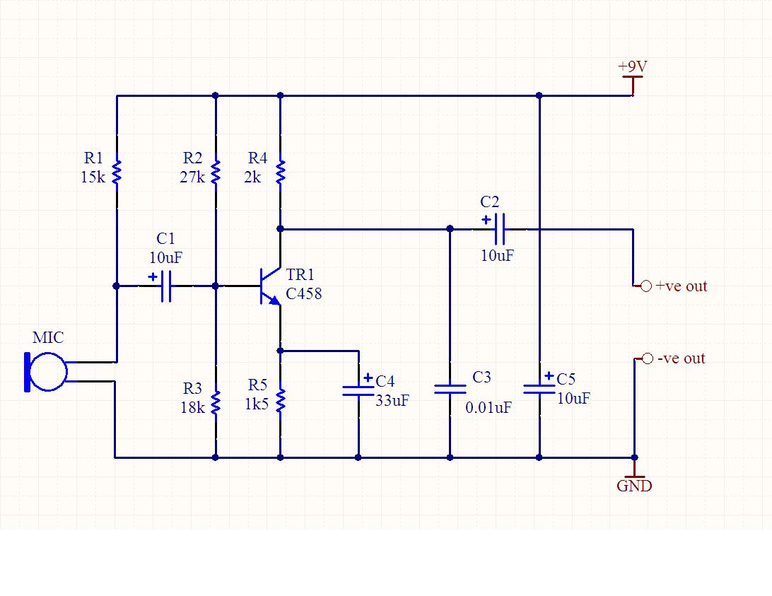
I would like to know if there is a way to reduce noise after mic preamp?
I am dealing with RF input where I have to give input through condenser mic then I preamp the signal. All I got was irritating noise and also the signal voice.
Can someone tell me how to remove the noise and how to increase the voice signal?:cry:
 

use decoupling capacitor...(am not sure, but just try or wait for more replies)
or some times, the gain of preamp may be high and can cause distortion....
actually what is ur circuit?
 
  • Like
Reactions: canodw

    canodw

    Points: 2
    Helpful Answer Positive Rating
It is an amp for mic input for gsm module. Actually what I want to achieve is being able to pick up smooth voice signal at receiver's side when a call is being made.
As for now, after implementing preamp circuit before MICP1 and MICN1 mic input of gsm module , the result that I got was white noise.
How to reduce this noise?

---------- Post added at 11:41 ---------- Previous post was at 11:14 ----------

Hi here's my cct.


A condenser microphone or electret microphone?
If it IS a condenser, it will need to be powered, either by an internal battery or by 'phantom power'. If it is an electret, it will need a small biasing voltage, either from an internal battery or from the first stage of the pre-amp.
If you provide the wrong power, or no voltage at all, or if you provide power from two sources, you are very likely to get noise out of the pre-amp, but this isn't noise which you then try to remove, it should be dealt with at source.
Your circuit shows a DC bias being applied to the mic through R1, which is unlikely to be supplying 'phantom power' but may be intended to provide the bias which is required for electret microphones.
Please check that the microphone you are using is being powered appropriately - condenser and electret types have completely incompatible requirements.
If the microphone already has power supplied by an internal battery then you must remove R1.

That's a very simple preamplifier, and there's not much that CAN go wrong with it. It would be reassuring if you could provide the voltages which are present on the 3 terminals of the transistor and confirm exactly which transistor part number you have used. Thanks.
 
Last edited:

Hi DXNewcastle,

How to tell the mic is condenser or electret? I just bought randomly from electronics store.
But in my case, I believe mine is condenser since the seller convinced it.
By the way, can you explain a bit more on phantom power?
The noise that I got is on and off. Suddenly it is there then the other it is gone.
Actually I am using BC458 npn transistor. Sorry for the typo error in the circuit.
 

You can look up "Phantom Power" on the internet. It is a method of passing the DC power supply voltage to the electronic circuit inside a microphone down the same 3-wire cable that is used for sending the audio signal in the opposite direction, from microphone to pre-amp. It is a method widely across the audio industry but it is not common in domestic equipment.

There are 3 types of microphone in common use: Dynamic (which requires no power, and can be very noisy if power is applied), Condensor/Capacitor (which will include a small electronic circuit and which must be powered, either from an internal battery or by phantom power from the pre-amp), or Electret (which only requires a small DC polarising voltage and will be noisy or silent without. This may be provided by a small internal battery).
It should be possible to tell which of these 3 you are using by reading what is printed on the microphone or reading the information supplied with it (either on a leaflet or on the packaging). If there is a battery compartment in the microphone then the battery voltage may be another clue to which type it is, but if there is NOT a battery compartment, then we can draw no conclusions.

We cannot help you much more until we know whether the circuit you have posted is the correct powering arrangement for your microphone. As I've laready pointed out - your circuit is supplying a DC voltage through R1, perhaps that voltage is necessary and perhaps it will just be providing noise.

It would still be helpful to know what voltages you see on the 3 pins of the transistor, both when the circuit is quiet and when it is noisy. Thanks.
 

Hi,

"We cannot help you much more until we know whether the circuit you have posted is the correct powering arrangement for your microphone. As I've laready pointed out - your circuit is supplying a DC voltage through R1, perhaps that voltage is necessary and perhaps it will just be providing noise."


Is that mean that I have to identify the correct type of microphone to be use with my pre-amp circuit? Forgive me, I just dont get the idea of what you say as my English is not that good.:oops:


About the transistor's 3 pin voltages, I'll post you in some other time since the testing circuit is in my lab and I need to go back there again tomorrow in order to know the values. Perhaps as soon as possible.
 

Is that mean that I have to identify the correct type of microphone to be use with my pre-amp circuit?
Yes.
We can help you with the circuit, but we must know which type of microphone you are using.
It should say 'dynamic' or 'electret' or 'condenser' or 'capacitor' somewhere. It might have a battery compartment. You have to tell us.
 

Ok I am using condenser mic. That is for sure. It stated on the leaflet.
No it does not come with any battery compartment but it does state that we have to connect to the 9v battery power source.
 

Ok I am using condenser mic.
Now we're getting somewhere, thank you.
. . . . it does state that we have to connect to the 9v battery power source.
What does it say about how to connect to the 9volt battery?

Also, I can't find any data for a BC458 here, it seems to be a device intended for RF. Can you post its parameters, please?
We still need to know the results of your measurements of the circuit - I'd also like to know what gain stage is following the circuit you posted, there must be some other circuit with gain after the pre-amp. How much gain?
 

What does it say about how to connect to the 9volt battery?

It does not say anything but to hook the +9V and GND to the 9V power supply source mainly battery.

Also, I can't find any data for a BC458 here, it seems to be a device intended for RF. Can you post its parameters, please?
I posted a link under:
http://www.datasheetcatalog.org/datasheets/150/128424_DS.pdf

I'd also like to know what gain stage is following the circuit you posted, there must be some other circuit with gain after the pre-amp. How much gain?
I think the gsm module that I was going to use has already have opamp built in. I am not sure how to check the gain since the information they had given in its datasheet is too sparse. Can you give me a hint on how to identify its internal gain? by the way, I am using gsm module from Sirius Mobility. I am not hesitate to give you the datasheet since you look putting so much effort to help me on this matter.:-D

Just like what I have said before, I only manage to give you the value of the transistor pin once I get back to my lab which is happen to be tomorrow.:-|
 

It does not say anything but to hook the +9V and GND to the 9V power supply source mainly battery.
That is the part of your circuit which still puzzles me.
I would expect the microphone's instructions say more than that. It needs to specify the audio connections AND the powering connection, even if they share the same wiring - it must say something about both connections.
Does the leaflet tell you the output impedance of the microphone?


Some experiments for you:
With the microphone disconnected, measure the resistance between the microphone's 2 terminals.
Note how long it takes between powering up the circuit and when the noise starts. And how long before it stops.
When the noise starts, disconnect the microphone. Is the noise still there? Instead of connecting the microphone, connect a resistor to the input of the circuit (anything between 600 Ohms and 3k) should be useful. Is the noise there without the microphone?
Is there any R.F in or near your test equipment? If so, a small capacitor between the transistor's collector and base might prevent the RF from being superimposed on the audio and becoming audible later (something between 10pF and 100pF).
If you have some 'Freeze Spray', when the noise starts, spray the transistor. Does that stop the noise?
If you can borrow a dynamic microphone, disconnect one end of R1 and replace the capacitor microphone with the dynamic microphone. Is the circuit still noisy?

Can you give me a hint on how to identify its internal gain?
Inject an AC signal to its input then measure the AC signal firstly at the input and secondly at the output.
 
Last edited:

Hi,

Here is the result of the 3 transistor pin.
Before noise:
C= 2.21V
B= 7.04V
E= 2.56V
The result is just the same after noise start.

By the way, the noise starts 6s after powering up the circuit. The signal output before 6s is quite clear even a bit distorted. After 6s, all I heard was white noise and I barely heard the voice signal. I did try hook up the preamplifier circuit with the PC jack and the result is fine. It still can amplify signal even I talked from 2 metres away from the mic.

I already implemented all the ideas u have given but nothing succeed as the noise kept buzzing my ears. When the noise start, I disconnected the mic and stilll the noise is there. Implementing the resistor between the mic input also doesnt seem to work.:-(

About the distorted voice that I got, I think I overamplified the internal amplifier. Dont you think so?
 

Hi,

The circuit given in above post works pretty well, as I tested that while building RF transmitter. The reasons that may causing too much noise in output stage are listed below, kindly check and revert back in case of doubts

1. Electret mic's are easy to identify, look at it's back side, you may found 2 pins/Pads one of them is connected to (aluminum) body of mic. That is ground, another is signal output. where you are suppose to put that 15K Pullup.

2.My experience shows that sometime this 15K not works well with some of the electric mics, and u need to modify that below upto 4.7K. so better keep one preset there.

3. Try biasing the transistor with 15K pullup and 10K pulldown.

4.at output stage the 2K resistor may be replaced with 4.7K to 10K.

5. Best way to get optimum values is to simulate same circuit with 100Hz to 10-20Khz sine wave of ultra low voltage. check whether you are getting inverted clear sinewave without clipping. (clipping also results in noisy behavior )

6. Last but not the least is matching of output stage of your amp, to input stage of another circuit. That may result in distorted output.

Happy debugging.

Regards
Atul Undre
 

    V

    Points: 2
    Helpful Answer Positive Rating
1. Electret mic's are easy to identify, look at it's back side, you may found 2 pins/Pads one of them is connected to (aluminum) body of mic. That is ground, another is signal output. where you are suppose to put that 15K Pullup.

2.My experience shows that sometime this 15K not works well with some of the electric mics, and u need to modify that below upto 4.7K. so better keep one preset there.

3. Try biasing the transistor with 15K pullup and 10K pulldown.

Do you have circuit for this? I hardly sum up every thing s u just explained.:-|
Thank you.

Best way to get optimum values is to simulate same circuit with 100Hz to 10-20Khz sine wave of ultra low voltage.
How to simulate this? Is it by using software or what?

matching of output stage of your amp
How to tell this?

---------- Post added at 09:04 ---------- Previous post was at 09:02 ----------

By the way, by observing the circuit which mic type do you think suits with the circuit? Electret or condenser?
 

Hi,

1. To simulate the circuit I used Multisim student edition, you may grab any other you find suitable, or try online Circuit Simulator Applet

2. Condenser/Electret Mics are configured in similar way, just in case of condenser mic you get extra terminal, dont get much bothered, as your design is for Electret Mic. 2 pin aluminum case mostly.

3. Matching is the most critical part always overlooked by many of us :), matching means => Impedenses of both side of network get matched i.e. they become identical. In case of amplifiers it is expected that input impedance to as high as possible and output impedance be as low as possible. In your case that is handled by C3 during active stage.

4. Spirit Communication; Making Waves | COMMERCIAL INDIGNATION shows images of electret mic
 

Interesting results!

1. The voltages on the transistor indicate that, either, the transistor has been damaged, or perhaps you have got them mixed up. The collector should be the most positive and the base just 0.7 volts more positive than the emitter. Please re-check. If the collector really is the most negative terminal then the transistor must be replaced.

2. We still don't know the impedance of the microphone, but your results after you replaced the microphone with a resistor suggests that C1 is being reverse biased. (What value of resistor did you use?). Depending on the type of capacitor you are using, a reverse bias on the capacitor may be the cause of the noise. Use your meter to see which end of C1 is most positive when the microphone is connected, and reverse it if necessary.

3. I still do not know what bias is required by your microphone - Love_Electronics is correct to suggest that R1, the 15k powering resistor may be completely wrong for your microphone, but until we know what power is required by your microphone, we can only guess.
But I disagree about biasing the transistor with 15k and 10k, becuase the bias is already provided by R2 and R3.
If there is no information supplied with the microphone then perhaps you just have to experiment with lower currents (increasing R1).

4. If you have written the correct voltages on the transistor, but written the wrong pin, then maybe its the base that is 2.56v. If that is correct, it suggests there's too much bias current. I expect that would lead to thermal noise, which would only become apparent after a short time, so R2 must be increased.

Please check look at these 4 points in order.
 
Last edited:

the transistor has been damaged, or perhaps you have got them mixed up

I tried hook the preamp up at PC jack, it works fine as it amplifies great signal with minimal noise and continuously works . The result is vice verse when I hook it up at my GSM module.

(What value of resistor did you use?)
I use 3k.

Depending on the type of capacitor you are using, a reverse bias on the capacitor may be the cause of the noise. Use your meter to see which end of C1 is most positive when the microphone is connected, and reverse it if necessary.
I use e-cap 16V and its most positive end is properly connected to the positive end of microphone.

Just one thing that I would like to stress out here, why on earth does the preamp only works in the first 6s? Was it just like what you said? Thermal noise?

---------- Post added at 14:57 ---------- Previous post was at 14:00 ----------

Holly crap!
I overlooked the datasheet. I was actually referring to BC548 instead of BC458 the one that I use. That was why I got the right value but at the wrong pin. Yes you are right.
E= 2.21V
C= 7.04V
B= 2.56V

Am so sorry bro for confusing you:oops:
 

Status
Not open for further replies.

Similar threads

Part and Inventory Search

Welcome to EDABoard.com

Sponsor

Back
Top