Continue to Site

Welcome to EDAboard.com

Welcome to our site! EDAboard.com is an international Electronics Discussion Forum focused on EDA software, circuits, schematics, books, theory, papers, asic, pld, 8051, DSP, Network, RF, Analog Design, PCB, Service Manuals... and a whole lot more! To participate you need to register. Registration is free. Click here to register now.

Jfet 87-108MHz FM Oscillator

Status
Not open for further replies.

geotFM

Junior Member level 3
Joined
Sep 19, 2017
Messages
29
Helped
0
Reputation
0
Reaction score
0
Trophy points
1
Activity points
276
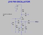
Hello.I am trying to build a simple fm oscillator based around j310 but i want some help with the values of the parts in order to tweak it for good harmonic profile.Can you help?
I am looking for best values for C1,C2,C3,L1,R5.Are L1,C3 needed?

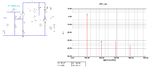
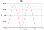
I am also attaching the LTSpice file simulation :smile:
 

Attachments

  • j310 OSC.jpg
    j310 OSC.jpg
    60.8 KB · Views: 394
  • j310Oscillator.zip
    903 bytes · Views: 79
Last edited:

I have never seen your oscillator circuit before. Almost all low power FM transmitters use a modified Colpitts circuit with an ordinary transistor like this:
 

Attachments

  • FM transmitter tweaked.png
    FM transmitter tweaked.png
    29.8 KB · Views: 247

I designed this oscillator for a relatively wide-band around 100MHz.If you wish, use it because it has a good performance.
100MHz_Collpits.png
 

Your transmitter has the antenna connected to the tuned LC circuit of the oscillator then anything that moves towards or away from the antenna will change the capacitance and change the frequency. My FM transmitter uses an RF amplifier in between the oscillator and the antenna so that the frequency does not change.
 
For good harmonic performance, you want to load the oscillator tank as little as possible.

The circuit below uses another J310 as a buffer amp whose output can easily be fed to more amplifying stages. As can be seen there is very good suppression of higher-order harmonics. While simulations give an idea of what to expect, final tuning and verification of your design should be done with the aid of a spectrum analyzer.
 

Attachments

  • jfet_osc.png
    jfet_osc.png
    69.1 KB · Views: 196

That is close.

P1 := 1.2E-3 (Power in Watt)
P2 := 0.5E-6
P3 := 0.8E-6
P4 := 0.3E-6

THD% := SQRT((P2 + P3 + P4)/P1)*100

THD% =[3.65]
 

Attachments

  • v_out.png
    v_out.png
    40.8 KB · Views: 113

Status
Not open for further replies.

Part and Inventory Search

Welcome to EDABoard.com

Sponsor

Back
Top