TheMaksimys
Newbie
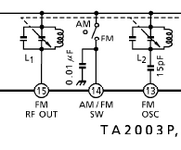
While working on the DIY project I came across FM ICs (such as TEA5710, TA2003, KA2246) that have two oscillators that are tunable to the tagreted frequency. The frequency of both are quite close if not to say that they are the same. For example here is the TA2003 with two pins devoted for these oscillators (Fig1).
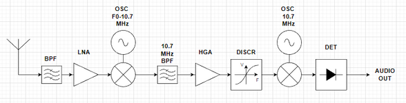
I do acknowledge that modern FM uses heterodyne type receviers, meaning they have to use two oscillators, namely at 10.7 MHz and F0+-10.7 MHz, where F0 is the frequency of the broadcast station. I have sketched the rough FM reciever system layout to demonstrate these oscillators (Fig2).
Could you, please, explain what exactly FM RF OUT and FM OSC are in terms of block schematic? Did I made a mistake in it or is it not complete to demonstrate both of these oscillators (FM RF OUT and FM OSC)? If so, could you correct me and explain what is the purpose of them?
Thank you very much! This question occupies my mind for a long time now.