Continue to Site

Welcome to EDAboard.com

Welcome to our site! EDAboard.com is an international Electronics Discussion Forum focused on EDA software, circuits, schematics, books, theory, papers, asic, pld, 8051, DSP, Network, RF, Analog Design, PCB, Service Manuals... and a whole lot more! To participate you need to register. Registration is free. Click here to register now.

16 bits to parallel port

Status
Not open for further replies.

panther2005

Junior Member level 1
Joined
Nov 3, 2011
Messages
15
Helped
1
Reputation
2
Reaction score
1
Trophy points
1,283
Activity points
1,372
Hi,
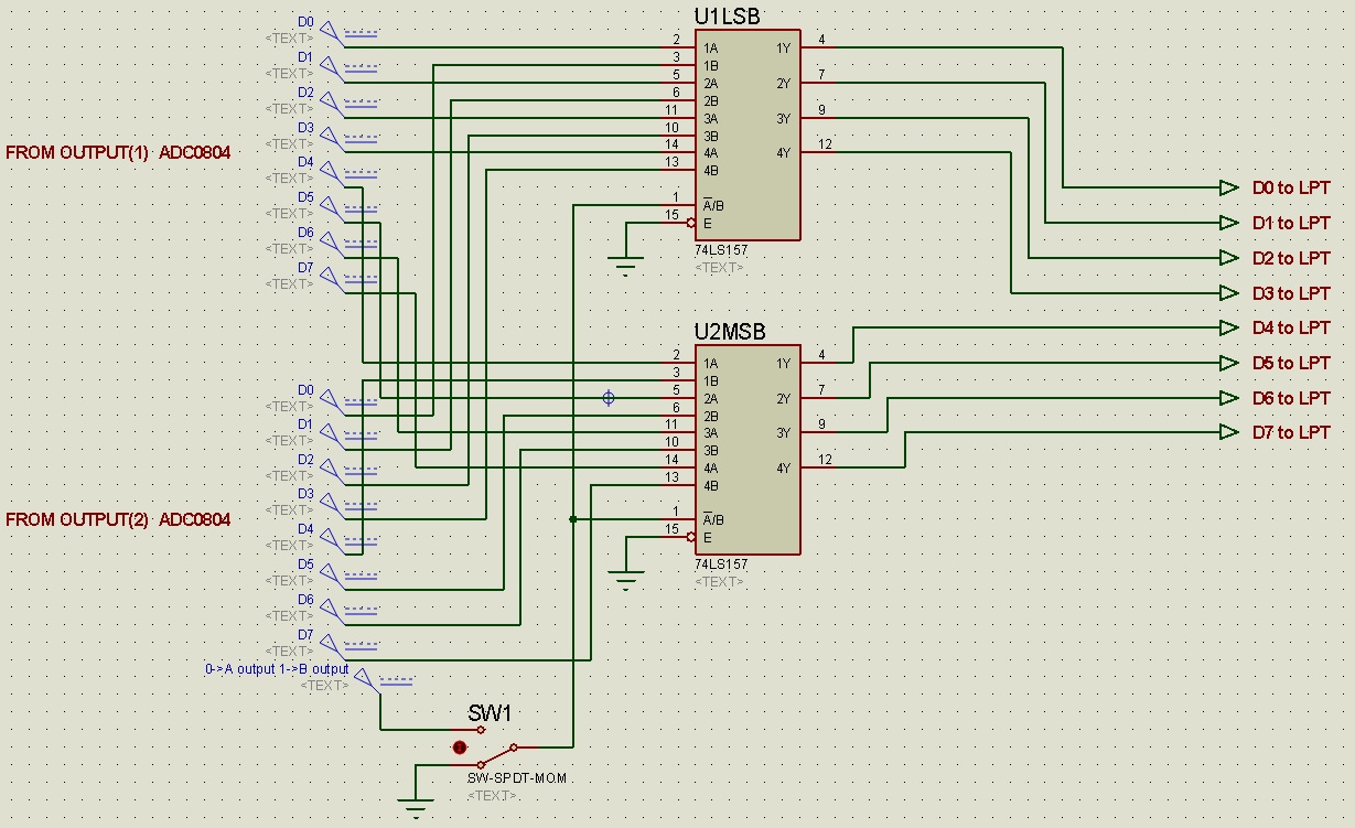
i want to send 16 bits , 8 bits then 8 bits via parallel port from 2 ADC to computer,
I don't want to use analogical MUX with one ADC, maybe a logical MUX with 2x8 bits input before sending to the parallel port (something like tri-state driver)
plz help me as soon as
circuit plz
 

What ADCs are you using, what MCU... some info to start with would be nice.
 

The ADC0804 has a chip select(SC) and a read/write signal. The /CS/WE/RD signals must come from an output port or from a databus. The /CS for each must be decodes out of the address space if you use a data bus connection. If you want to read it through the microcontroller IO-ports you must generated the readout timing in software.
 

You can connect in parallel the outputs of both ADC, and use CS pins to read one after the other.

I've never dealt with parallel port before, so I'm guessing here that, since the parallel port uses TTL levels, you can connect them directly to the data lines of the port, and use status lines for controlling the ADC's.
 

yes, but if I connect the both ADC output i will have the data confusion in the output ( the last value of ADC still exist in the output and not in high impedance or opened collector))
 
  • Like
Reactions: deniah

    deniah

    Points: 2
    Helpful Answer Positive Rating
you can use bus transceiver with tristate like 74HC245 to tristating the output of ADC, and then connect in parallel the output of both 74HC245 to micro...
 
Datasheet snip: "When data is to be read the combination of both CS and RD being low will reset the INTR F/F and will enable the TRI-STATE buffer latch output onto the 8-bit data bus"

There shouldn't be any collision as long at least one of ADCs is in tri-state mode (CS or RD high).
 
thanks for all replies

i will try with 74HC245
 

I am confused because the datasheets shows that the output will go into tri-sate if you have /CS at a logic high level. So not busbuffer are needed, if the /CS is used.
 

I am confused because the datasheets shows that the output will go into tri-sate if you have /CS at a logic high level. So not busbuffer are needed, if the /CS is used.

HTA
ie I can connect in parallel the outputs of both ADC!!

---------- Post added at 16:43 ---------- Previous post was at 16:42 ----------

what about this circuit:

https://obrazki.elektroda.pl/86_1165665144.JPG
 

Hi panther

the circuit you shows is a bus multiplexer with input register. The bus buffer is only needed if you want to driver onger lines. Is this the case? If the connections between the ADC and the micro is on the same board the connection can be made directly to the bus or ports. If you want such a kind of bus multipler with connector the LS373 is beening replaced by the ADC.
 
If the parallel printer port is in SPP mode, the data lines act like output lines.
How to use the parallel port as input port without conflicting other things.
Beyondlogic gives details on printerport usage. below is the link:

**broken link removed**
 

Aha, so interfacing the ADCs to a printer port to read it out is what you want to do? If so, the document you have describes several principle methods, however it is not clear what kind of printerport you want to connect with?
 

Whichever is convenient and workable. SPP requires using input port four pins at a time, two nibbles for each byte. All the latest PC's have advance ports supporting 8 bit data read write. The link I posted gives EPP and ECP modes but I could not succeed in successfully using it at its full capability of 8 bits at a time.

Some tricky configuration is involved that I could not get it seems.
 

It is difficuilt for me to guess what it did not work. I know product which work this way. A few basic things comes to my mind which you could look at: the ADC needs to be initializes and a convertion start. The parallel port must be delayed until the ADC data is ready(/BUSY and nAk signal). The timing diagramm of the ADC read write must be met.

Good look!
 

the problem is resolved :)

now i can mesure 2 inputs (x,y) with the same time (by using both WR) without shift between x and y points


thanks for all
 

Status
Not open for further replies.

Similar threads

Part and Inventory Search

Welcome to EDABoard.com

Sponsor

Back
Top