Continue to Site

Welcome to EDAboard.com

Welcome to our site! EDAboard.com is an international Electronics Discussion Forum focused on EDA software, circuits, schematics, books, theory, papers, asic, pld, 8051, DSP, Network, RF, Analog Design, PCB, Service Manuals... and a whole lot more! To participate you need to register. Registration is free. Click here to register now.

[SOLVED] Controlling 16 Leds using LPT Port and two 74HC595 Shift Registers

Status
Not open for further replies.

gohoto99

Newbie
Joined
Aug 31, 2023
Messages
5
Helped
0
Reputation
0
Reaction score
0
Trophy points
1
Activity points
46
Hi guys!
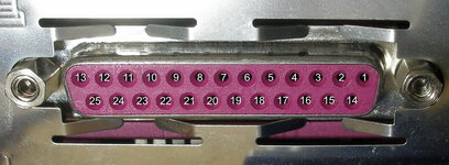
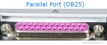
So i need a little bit of help. Im doing a project where i have to create a scheme which controls 16 Leds using LPT Port. For that im using two 74HC595 shift registers. I also need to write a program in C/C++ which lights up a certain led, makes all ON and/or all OFF. Im in need of help how to connect the parts together.
Thanks!
 

I don't recall PC interface simpler than the parallel one; anyway, I wonder if any OS in the world still provide support for such standard, even if it's still legacy in Windows Device Manager.

Im in need of help how to connect the parts together.

Did you even do a sketch of your diagram ?
Are you aware that any shift register IC can be cascaded output from one to input of the other ?
 
Last edited:

I don't recall PC interface simpler than the parallel one; anyway, I wonder if any OS in the world still provide support for such standard, even if it's still legacy in Windows Device Manager.


Did you even do a sketch of your diagram ?
Are you aware that any shift register IC can be cascaded output from one to input of the other ?
Hi, i know it sound that old but my assignment strictly says to use that LPT Port (DB25) which bugs me out.
So this would be my curcuit, but i have no clue how to connect my arduino to my LPT port or if it's even possible..

ShftOutExmp2_3.gif
 

Could you take an actual picture of the LPT (DB25) connector you are referring to? Please don't get me wrong, I just don't want to spend time on something that doesn't feel right.( I need to see it with my eyes there is still one in the world..lol ). Is it native to the motherboard or is it an expansion card for example. PCI?
 

I get you and i'm sorry, it's an assignment from my university. Here are some pictures.
 

Attachments

  • 350px-Parallel_port_pinouts.svg.png
    350px-Parallel_port_pinouts.svg.png
    20.9 KB · Views: 60
  • _pinsnum.jpg
    _pinsnum.jpg
    118.6 KB · Views: 70
  • parallel-port.jpg
    parallel-port.jpg
    30.9 KB · Views: 63

This is what my assignment says: To develop a program to control 16 LEDs through the LPT port of a personal computer. The program should be able to turn on/off a given LED given as a parameter - number of the LED and state "on" or "off". Also provide a command to globally turn on all LEDs or globally stop all LEDs. When changing the state of a given LED, the state of the other LEDs should not change.
With all that, i have to make a physical circuit and show my professor that it work's.
 

You would use 1 pin from arduino as a chip select for which of the two
595 you want to stuff data into.

Then read the LPT port to get data.

You would use two pins to control the output enables of the 595's. So your
code routine would present a bit to ser pin, then toglle the clock pin, then
after 8 loads re-enable output.

OR

Cascade the two chips to create 1 16 bit SR, enable both, turn off output enable
on both pins (now just 1 arduino pin, do 16 loads, then turn on ouput enable to
both chips.

How do you know what 8 bit value is in LPT port for which 595 ? is it a burst of two
bytes then a long delay between burst so you could figure out which byte goes to
which 595 ?


Regards, Dana.
 

I expected to see a picture of this connector on your PC, whatever. Ok, as said, you can cascade Shift Registers, so you could use one pin of the connectr as the Clock, and other 8 as output, so as said, sketch the diagram, read the IC datasheet, its quite simple. In electronics, it turn things easier to undetand/talk about with the schematic.
 

If assignment requires using PC LPT-port, how comes Arduino into play?

Controlling LPT is well possible, with protected mode OS (e.g. Windows) you need a driver to enable port access from user mode application. With Windows 2000 we used giveio.sys, don't know if it still works under Windows 10/11.
 

First you say PC, then you say Arduino.What are you talking about?? Why do you need to connect an Arduino to your parallel port?

I'm totally lost.
 

I need it without Arduino. I thought it can be done only using some kind of board that's why i published the image.
 

Hi,

You did not draw the Arduino circuit on your own, nor you took the LPT photos on your own.

It would be encouraging if we saw what you did so far.

Klaus
 

ASSUMING you can actually talk to your LPT:
1) Cascade the shift registers
2) Connect D0 of LPT to the input of the first SR
3) Use D1 as a clock
4) Use D2 as reset
 

I would do it differently. The LPT port has 8 data bits and several control lines. Each has a hardware (or virtual) address. I would use two octal latches, they generally have a higher output current capability than a HC595, then wire their latch enables to two of the control lines.

Brian.
 

I would do it differently. The LPT port has 8 data bits and several control lines. Each has a hardware (or virtual) address. I would use two octal latches, they generally have a higher output current capability than a HC595, then wire their latch enables to two of the control lines.

Brian.
Thought about that, but didnt know you can directly access the control lines. But, if you can, then two latches and two latch_enable signals is definitely the easy way to go.

But overall, what a waste of time. When are you ever going to need to know how to access a long-obsolete LPT?
 

Hi,

I see it as a kind of school project and it´s not to find a better solution, but to solve the task with using the LPT and the HC595 to control the LEDs.

Still it´s some kind of homework ... and the OP does not show what he has done so far.

Klaus
 

Hi,

I see it as a kind of school project and it´s not to find a better solution, but to solve the task with using the LPT and the HC595 to control the LEDs.

Still it´s some kind of homework ... and the OP does not show what he has done so far.

Klaus
It's obviously a homework, but why train your students to design something based on obsolete technology? Do they draw their schematics on papyrus with a quill?
 

I interviewed someone recently, straight out of university with a degree in electronics. I asked them to explain DMA and they had never heard of it, they had heard of interrupts but didn't know what they were but they did know all about analog circuits because they studied 741 op-amps in class.

...and yes the control lines are all just I/O at the adjacent port number.

Brian.
 

but why train your students to design something based on obsolete technology? Do they draw their schematics on papyrus with a quill?k
Maybe because the teachers are outdated?
Or just to see how the students perform.
 

Status
Not open for further replies.

Part and Inventory Search

Welcome to EDABoard.com

Sponsor

Back
Top