I/Q Imbalance
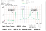
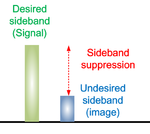
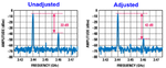
As mentioned above, for SSB modulation, there should be only one desired sideband in the spectrum in theory.
Nevertheless, in reality, there will be at least three tones in the spectrum.
As shown below, one of the three tones is undesired sideband, so-called image .

The undesired sideband, so-called image, resulting from I/Q imbalance .
Especially, in the case of broadband operation, compared to the narrowband case,
the I/Q imbalance among the differential I/Q input channels becomes more serious and thus brings about the image product, which aggravates the system performance .
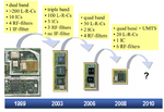
Direct up-conversion (DUC) transmitter has the inherent advantage of conceptual simplicity and high integration level .
Thus, it has become popular in recent years , especially for handset device, e.g. cellphone.

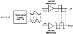
As illustrated below , the DUC, just as its name implies, baseband converts to RF directly.

To assure high signal quality,
the ideal IQ modulator would have perfectly symmetrical in-phase and quadrature arms .
That is to say,
in theory, the I and Q channels should have identical gains, and should be exactly 90º out of phase.
For DUC transmitter, due to the high frequency of the LO, it is not possible to implement the IQ modulator digitally.
Nevertheless, while developers strive for a symmetrical IQ modulator circuit, manufacturing process variations cause slight differences between the in-phase and quadrature paths on the same die.
Besides, an analog IQ modulator exhibits gain and phase imbalances between the two branches .

In other words,
in a practical DUC quadrature modulator,
the I and Q channels may have different gains and the LO signals may not be exactly 90◦ out of phase .
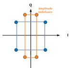
The symptom that I and Q channels have different gains is I/Q gain imbalance, or I/Q amplitude imbalance.
And the symptom that I and Q channels are not exactly 90◦ out of phase is I/Q phase imbalance.
Both I/Q gain and phase imbalance are known collectively as I/Q imbalance.
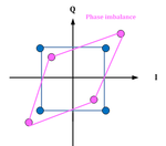
In terms of constellation, as illustrated below :


Of course, due to constellation distortion, I/Q imbalance results in EVM degradation and degrades modulation accuracy.
In addition, as mentioned above, I/Q imbalance leads to undesired sideband(i.e. image) .
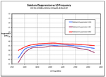
The amplitude difference between signal and image is defined as sideband suppression.

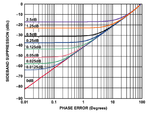
The following figure shows a plot that can be used to relate sideband
suppression to I/Q gain imbalance and quadrature imbalance.
It is notable in this example that improving the quadrature phase imbalance has no effect on the sideband suppression unless the gain imbalance is also improved .

In other words, generally speaking,
I/Q gain imbalance has more effect on sideband suppression than I/Q phase imbalance.
Although the I/Q imbalance is inevitable, we are able to diminish it as much as possible.
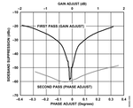
We can make use of the fact that the sideband suppression can be optimized by adjusting phase and amplitude offsets between I and Q channel .

As shown in the figure above,
in the first pass, the gain delta between I and Q is adjusted.
The sweep yields a null of around −57 dBc for a gain difference of approximately −0.1 dB.
Next, adjust the skew between I and Q.
This drives the null down further to −60 dBc for a phase adjust of −0.05°.
In this case, the first-pass gain adjust yields a deep trough that is only slightly improved during the phase sweep.
The phenomenon proves that I/Q gain imbalance has more effect on sideband suppression than I/Q phase imbalance again, as mentioned above.
Thus, gain and phase need to be adjusted consecutively in several steps until the undesired sideband leakage is minimized.
In terms of frequency domain, the sideband suppression does improve with adjustment.

Besides, in the RF scenario, to alleviate the performance degradation caused by the image product,
attention should be paid to the PCB layout process where the differential I/Q channels should be identical in their physical layout.
Both Tx I/Q and Rx I/Q signals adopt differential form to avoid being interfered by outside interference,
and then degrading the modulation and demodulation accuracy.

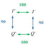
There will be four I/Q signals : I+、I-、Q+、Q-.
And the phase relationship is as shown in the figure below :

Ideally, the four traces on the IQ signal path from the DAC output to the modulator input should be symmetrical between the I channel and Q channel and between the positive side and negative side within a channel.
In reality, due to variations of PCB design rules and manufacturing limitations, trace lengths are not perfectly matched.
The mismatches cause the signal in one channel to be skewed from the other, and, therefore, result in IQ phase errors.
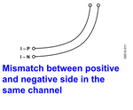
Typically there are two types of trace length mismatches as shown in the figure below :


Trace mismatches between I and Q channels degrade IQ phase imbalance.
Mismatches between the positive and negative side in a channel distort a differential signal by skewing the two sides away from 180° out of phase.
This causes both gain and phase imbalance.
Typically, the traces in a differential pair are laid out very close to each other.
Its potential mismatch is relatively small.
However, when the differential pair is long, every time it makes a turn on the PCB, the external trace adds a little bit more in the total length than the internal one.
It can accumulate to a certain level where the mismatch starts to have an impact on sideband suppression.
Thus, we have to make use of some methods to alleviate the mismatch caused by turns on the PCB.
As mentioned above, the I/Q imbalance is inevitable.
In terms of PCB, what we can do is to try our best to make the four I/Q signals (i.e. I+、I-、Q+、Q-) have identical lengths.
Of course, if possible, make the PCB trace lengths of the four I/Q signals as short as possible to reduce the potential mismatch. Otherwise, the sideband suppression will aggravate.

Besides, we should consider the effect of temperature as well .
On the whole, lower the temperature, more the sideband suppression.

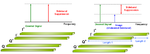
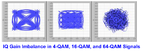
Higher-order modulation schemes such as 64-QAM are much more susceptible to IQ gain imbalance.
One easy way to visualise this effect is to observe a constellation plot of varying orders of modulation.

Thus, it is important to minimise gain or phase imbalance when designing an RFIC that supports complex modulation schemes.
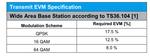
As illustrated in the figure above, several constellation plots with increasing orders of modulation and constant gain imbalance. Consequently, in LTE application,
the EVM specifications vary with modulation schemes due to the fact that 64QAM is the worst case in terms of modulation.

As mentioned above, for SSB modulation, there should be only one desired sideband in the spectrum in theory.
Nevertheless, in reality, there will be at least three tones in the spectrum.
As shown below, one of the three tones is undesired sideband, so-called image .
The undesired sideband, so-called image, resulting from I/Q imbalance .
Especially, in the case of broadband operation, compared to the narrowband case,
the I/Q imbalance among the differential I/Q input channels becomes more serious and thus brings about the image product, which aggravates the system performance .
Direct up-conversion (DUC) transmitter has the inherent advantage of conceptual simplicity and high integration level .
Thus, it has become popular in recent years , especially for handset device, e.g. cellphone.
As illustrated below , the DUC, just as its name implies, baseband converts to RF directly.
To assure high signal quality,
the ideal IQ modulator would have perfectly symmetrical in-phase and quadrature arms .
That is to say,
in theory, the I and Q channels should have identical gains, and should be exactly 90º out of phase.
For DUC transmitter, due to the high frequency of the LO, it is not possible to implement the IQ modulator digitally.
Nevertheless, while developers strive for a symmetrical IQ modulator circuit, manufacturing process variations cause slight differences between the in-phase and quadrature paths on the same die.
Besides, an analog IQ modulator exhibits gain and phase imbalances between the two branches .
In other words,
in a practical DUC quadrature modulator,
the I and Q channels may have different gains and the LO signals may not be exactly 90◦ out of phase .
The symptom that I and Q channels have different gains is I/Q gain imbalance, or I/Q amplitude imbalance.
And the symptom that I and Q channels are not exactly 90◦ out of phase is I/Q phase imbalance.
Both I/Q gain and phase imbalance are known collectively as I/Q imbalance.
In terms of constellation, as illustrated below :
Of course, due to constellation distortion, I/Q imbalance results in EVM degradation and degrades modulation accuracy.
In addition, as mentioned above, I/Q imbalance leads to undesired sideband(i.e. image) .
The amplitude difference between signal and image is defined as sideband suppression.
The following figure shows a plot that can be used to relate sideband
suppression to I/Q gain imbalance and quadrature imbalance.
It is notable in this example that improving the quadrature phase imbalance has no effect on the sideband suppression unless the gain imbalance is also improved .
In other words, generally speaking,
I/Q gain imbalance has more effect on sideband suppression than I/Q phase imbalance.
Although the I/Q imbalance is inevitable, we are able to diminish it as much as possible.
We can make use of the fact that the sideband suppression can be optimized by adjusting phase and amplitude offsets between I and Q channel .
As shown in the figure above,
in the first pass, the gain delta between I and Q is adjusted.
The sweep yields a null of around −57 dBc for a gain difference of approximately −0.1 dB.
Next, adjust the skew between I and Q.
This drives the null down further to −60 dBc for a phase adjust of −0.05°.
In this case, the first-pass gain adjust yields a deep trough that is only slightly improved during the phase sweep.
The phenomenon proves that I/Q gain imbalance has more effect on sideband suppression than I/Q phase imbalance again, as mentioned above.
Thus, gain and phase need to be adjusted consecutively in several steps until the undesired sideband leakage is minimized.
In terms of frequency domain, the sideband suppression does improve with adjustment.
Besides, in the RF scenario, to alleviate the performance degradation caused by the image product,
attention should be paid to the PCB layout process where the differential I/Q channels should be identical in their physical layout.
Both Tx I/Q and Rx I/Q signals adopt differential form to avoid being interfered by outside interference,
and then degrading the modulation and demodulation accuracy.
There will be four I/Q signals : I+、I-、Q+、Q-.
And the phase relationship is as shown in the figure below :
Ideally, the four traces on the IQ signal path from the DAC output to the modulator input should be symmetrical between the I channel and Q channel and between the positive side and negative side within a channel.
In reality, due to variations of PCB design rules and manufacturing limitations, trace lengths are not perfectly matched.
The mismatches cause the signal in one channel to be skewed from the other, and, therefore, result in IQ phase errors.
Typically there are two types of trace length mismatches as shown in the figure below :
Trace mismatches between I and Q channels degrade IQ phase imbalance.
Mismatches between the positive and negative side in a channel distort a differential signal by skewing the two sides away from 180° out of phase.
This causes both gain and phase imbalance.
Typically, the traces in a differential pair are laid out very close to each other.
Its potential mismatch is relatively small.
However, when the differential pair is long, every time it makes a turn on the PCB, the external trace adds a little bit more in the total length than the internal one.
It can accumulate to a certain level where the mismatch starts to have an impact on sideband suppression.
Thus, we have to make use of some methods to alleviate the mismatch caused by turns on the PCB.
As mentioned above, the I/Q imbalance is inevitable.
In terms of PCB, what we can do is to try our best to make the four I/Q signals (i.e. I+、I-、Q+、Q-) have identical lengths.
Of course, if possible, make the PCB trace lengths of the four I/Q signals as short as possible to reduce the potential mismatch. Otherwise, the sideband suppression will aggravate.
Besides, we should consider the effect of temperature as well .
On the whole, lower the temperature, more the sideband suppression.
Higher-order modulation schemes such as 64-QAM are much more susceptible to IQ gain imbalance.
One easy way to visualise this effect is to observe a constellation plot of varying orders of modulation.
Thus, it is important to minimise gain or phase imbalance when designing an RFIC that supports complex modulation schemes.
As illustrated in the figure above, several constellation plots with increasing orders of modulation and constant gain imbalance. Consequently, in LTE application,
the EVM specifications vary with modulation schemes due to the fact that 64QAM is the worst case in terms of modulation.