For
I/Q signal
I/Q imbalance
carrier leakage
you can refer to the PDF file
Introduction to I/Q signal
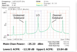
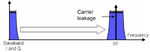
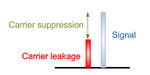
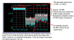
As mentioned above, for SSB modulation, in reality, there will be at least three tones in the spectrum.
One is signal(i.e. desired sideband), another is undesired sideband(i.e. image),
and the other is carrier leakage(i.e. LO leakage).
Carrier leakage is also known as carrier feedthrough and I/Q origin offset, mainly results from two factors :
 LO leakage
 DC Offset of I/Q channels.
To get low conversion loss from a passive mixer, typically a high LO power is needed.
Due to the finite mixer port to port isolation, and strong LO power,
the LO signal can leak through the RF port, which may result in significant LO leakage .

Besides, excessive DC offsets in I/Q channels cause high levels of carrier leakage as well .
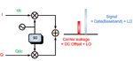
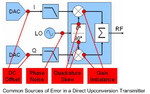
In DUC transmitter, with LO, baseband converts to RF directly.
Thus, if there are DC offsets in I/Q channels, with LO, DC offsets converts to LO leakage directly as well.

In terms of constellation, as illustrated below:

Of course, due to constellation distortion, DC offsets in I/Q channels result in EVM degradation and degrades modulation accuracy.
As mentioned above, in the case of broadband operation, compared to the narrowband case,
the I/Q imbalance becomes more serious.
Similarly, the carrier leakage becomes more serious in the case of broadband operation.


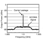
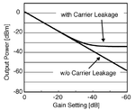
As shown in the figure above, in the case of broadband operation and DUC transmitter, the carrier leakage and signal overlap.

Without countermeasures, the carrier leakage stays constant while the signal is reduced.
Therefore, as shown in the figures above, in low power mode,
the carrier leakage is even larger than signal, which degrades SNR.
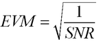
As illustrated below, EVM varies inversely with SNR :

That is to say, with carrier leakage,
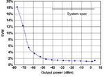
EVM begins to exceed the set limit when too much gain reduction is exercised, less the output power, higher the EVM .

Thus, in LTE application, the LO leakage specifications vary with output power .

In WCDMA application, the step E and step F of Inner Loop Power Control (ILPC) need 73 dB dynamic range(-50 dBm ~ 23 dBm).
Nevertheless, as shown in the figure below, with carrier leakage,
it is impossible for the output power to be lower than -30 dBm.
That is to say, the carrier leakage may reduce the dynamic range and make ILPC fail.

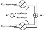
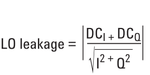
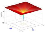
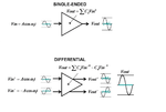
Of course, ideally, without DC offsets in I/Q channels, there should be completely no carrier leakage, as shown in the formula below :

Or as shown in the figure below :

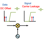
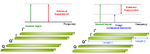
Nevertheless, carrier leakage is inevitable, and can’t be rejected by means of DC block :

As illustrated above, the DC block is a high pass filter. Before mixer, both the DC offset and baseband data are rejected.
Whereas after mixer, both the DC offset and baseband data pass the DC block.
Thus, DC block is not the solution to carrier leakage.
In order to solve the carrier leakage issue, some transceivers integrate calibration circuit .
For example, the BCM4356 of Broadcom integrates LO feedthrough (LOFT) calibration circuit.
The amplitude difference between signal and carrier leakage is defined as carrier suppression.

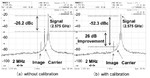
In terms of frequency domain, afrter calibration, the carrier suppression improves indeed .

In a typical RF transmitter implementation, individual components, including the digital-to-analog-converter are subject to slight errors in gain and DC offset.
Thus, when considering a DAC or direct quadrature modulator,
it is important to apply gain or DC offset adjustments to the baseband I or Q signals.
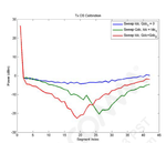
Take RTR6285A of Qualcomm for example, after iterative adjustment of the DC offset of the I/Q differential input, the carrier suppression improves indeed, as shown below :

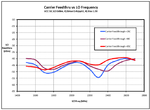
As mentioned above, for I/Q imbalance, we should consider the effect of temperature.
Similarly, for carrier leakage, we should also consider the effect of temperature.

In LTE application, both image suppression and carrier suppression are included in in-band emission requirements .


As mentioned above, in terms of PCB,
what we can do is to try our best to make the four I/Q signals (i.e. I+、I-、Q+、Q-) have identical lengths. Fortunately, this method improves not only sideband suppression, but also carrier suppression.

If the IQ modulator has perfectly symmetrical in-phase and quadrature arms, the DC offset will cancel.

This is the reason why we should try our best to make the four I/Q signals have identical PCB layout trace lengths.
Of course, similarly, if possible, make the PCB trace lengths of the four I/Q signals as short as possible.
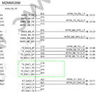
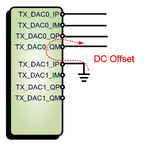
Besides, don’t short those unused I/Q pins to ground.
For example, the MDM9X35 of Qualcomm :

As shown above,
TX_DAC1_IP
TX_DAC1_IM
TX_DAC1_QP
TX_DAC1_QM
these four pins are unused.
Because these I/Q pins are all related within chip.
If you short the four unused pins to ground, the DC offset on the ground will flows into these unused pins,
then leakages to the used I/Q pins and generates carrier leakage.

Undesired sideband and carrier leakage are the inherent shortcomings of DUC transmitter.
As illustrated in the detailed figure below :

I/Q signal
I/Q imbalance
carrier leakage
you can refer to the PDF file
Introduction to I/Q signal
As mentioned above, for SSB modulation, in reality, there will be at least three tones in the spectrum.
One is signal(i.e. desired sideband), another is undesired sideband(i.e. image),
and the other is carrier leakage(i.e. LO leakage).
Carrier leakage is also known as carrier feedthrough and I/Q origin offset, mainly results from two factors :
 LO leakage
 DC Offset of I/Q channels.
To get low conversion loss from a passive mixer, typically a high LO power is needed.
Due to the finite mixer port to port isolation, and strong LO power,
the LO signal can leak through the RF port, which may result in significant LO leakage .
Besides, excessive DC offsets in I/Q channels cause high levels of carrier leakage as well .
In DUC transmitter, with LO, baseband converts to RF directly.
Thus, if there are DC offsets in I/Q channels, with LO, DC offsets converts to LO leakage directly as well.
In terms of constellation, as illustrated below:
Of course, due to constellation distortion, DC offsets in I/Q channels result in EVM degradation and degrades modulation accuracy.
As mentioned above, in the case of broadband operation, compared to the narrowband case,
the I/Q imbalance becomes more serious.
Similarly, the carrier leakage becomes more serious in the case of broadband operation.
As shown in the figure above, in the case of broadband operation and DUC transmitter, the carrier leakage and signal overlap.
Without countermeasures, the carrier leakage stays constant while the signal is reduced.
Therefore, as shown in the figures above, in low power mode,
the carrier leakage is even larger than signal, which degrades SNR.
As illustrated below, EVM varies inversely with SNR :
That is to say, with carrier leakage,
EVM begins to exceed the set limit when too much gain reduction is exercised, less the output power, higher the EVM .
Thus, in LTE application, the LO leakage specifications vary with output power .
In WCDMA application, the step E and step F of Inner Loop Power Control (ILPC) need 73 dB dynamic range(-50 dBm ~ 23 dBm).
Nevertheless, as shown in the figure below, with carrier leakage,
it is impossible for the output power to be lower than -30 dBm.
That is to say, the carrier leakage may reduce the dynamic range and make ILPC fail.
Of course, ideally, without DC offsets in I/Q channels, there should be completely no carrier leakage, as shown in the formula below :
Or as shown in the figure below :
Nevertheless, carrier leakage is inevitable, and can’t be rejected by means of DC block :
As illustrated above, the DC block is a high pass filter. Before mixer, both the DC offset and baseband data are rejected.
Whereas after mixer, both the DC offset and baseband data pass the DC block.
Thus, DC block is not the solution to carrier leakage.
In order to solve the carrier leakage issue, some transceivers integrate calibration circuit .
For example, the BCM4356 of Broadcom integrates LO feedthrough (LOFT) calibration circuit.
The amplitude difference between signal and carrier leakage is defined as carrier suppression.
In terms of frequency domain, afrter calibration, the carrier suppression improves indeed .
In a typical RF transmitter implementation, individual components, including the digital-to-analog-converter are subject to slight errors in gain and DC offset.
Thus, when considering a DAC or direct quadrature modulator,
it is important to apply gain or DC offset adjustments to the baseband I or Q signals.
Take RTR6285A of Qualcomm for example, after iterative adjustment of the DC offset of the I/Q differential input, the carrier suppression improves indeed, as shown below :
As mentioned above, for I/Q imbalance, we should consider the effect of temperature.
Similarly, for carrier leakage, we should also consider the effect of temperature.
In LTE application, both image suppression and carrier suppression are included in in-band emission requirements .
As mentioned above, in terms of PCB,
what we can do is to try our best to make the four I/Q signals (i.e. I+、I-、Q+、Q-) have identical lengths. Fortunately, this method improves not only sideband suppression, but also carrier suppression.
If the IQ modulator has perfectly symmetrical in-phase and quadrature arms, the DC offset will cancel.
This is the reason why we should try our best to make the four I/Q signals have identical PCB layout trace lengths.
Of course, similarly, if possible, make the PCB trace lengths of the four I/Q signals as short as possible.
Besides, don’t short those unused I/Q pins to ground.
For example, the MDM9X35 of Qualcomm :
As shown above,
TX_DAC1_IP
TX_DAC1_IM
TX_DAC1_QP
TX_DAC1_QM
these four pins are unused.
Because these I/Q pins are all related within chip.
If you short the four unused pins to ground, the DC offset on the ground will flows into these unused pins,
then leakages to the used I/Q pins and generates carrier leakage.
Undesired sideband and carrier leakage are the inherent shortcomings of DUC transmitter.
As illustrated in the detailed figure below :