konrad_3582
Newbie level 4
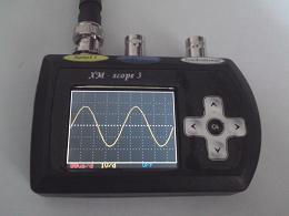
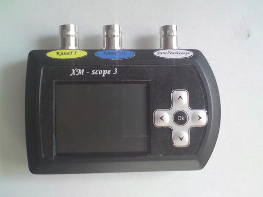
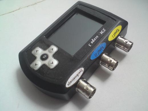
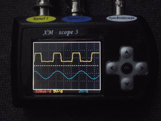
XM-scope 3 - miniature 2-channel digital oscilloscope for evryone
User drzasiek presents another, already the third version of digital oscilloscope with processor from the AVR family. This time the machnine is more complex, there are added a lot of interesting and useful features and above all, adding the device more practical applications.
The main goal of the project was to making a 2-channel oscilloscope with the smallest dimensions, with low hardware complexity, so that evryone can do it at home. An important role played the cost of implementation and availability of parts.
About device:
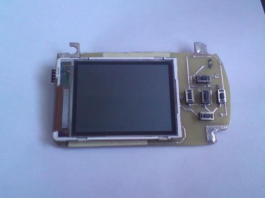
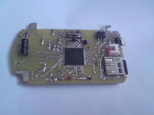
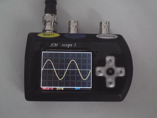
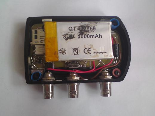
The device's heart is a microcontroller ATXMega 128A3-AU. The oscilloscope uses two built-in A/C converters of the microcontroller. The LCD display is a 132x176 pixels TFT with driver LS020 or L2F50 from popular cell phone Siemens S65/SX65/CX65 etc. Larger display is harder to use. LS020 is the simplest. Device control is available by five navigation keys.
Parameter description:
-max sample rate in real time: 2 Ms/s per channel
-max frequency equivalent-time sampling: 24 Ms/s
-amplitude resolution: 12 bits (11 bits + sign bit)
-input voltage range (AC: +/- 35V, DC 0-35V)
-analog band <1MHz
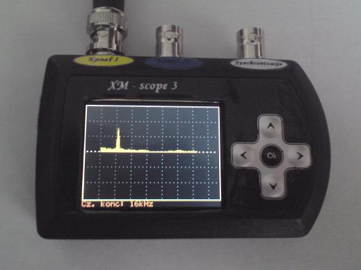
-frequency range measured waveforms in real time: 50Hz-250kHz per channel sinusoidal signals (or similar), periodic
-time-base in real time: 5us/d, 10us/d, 20us/d, 40us/d, 80 us/d, 160 us/d, 320 us/d, 640 us/d, 1.3 ms/d, 2.5 ms/d, 5 ms/d
-time-base in equivalent time: 1.6us/d, 800ns/d, 400ns/d
-voltage on the plot: 200mV/d, 0.5V/d, 1V/d, 2V/d, 5V/d, 10V/d, 20V/d (indipendent control for each channel)
Function description:
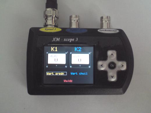
-The possibility of an indipendent regulatory probe attenuation (1x, 10x, 100x) for each channel which changes the voltage accordingly to the plot
-Stepless vertical position of each of the waveform on the screen
-Continuously adjustable trigger level
-Auto-synchronization (software) with respect to the selected channel or turn off synchronization
-Trigger key
-External-trigger signal (rising edge)
-External-trigger signal (trailing edge)
-Amplitude measurement for each channel
-Frequency measurement for each channel
-Maximum-value measurement process for each channel
-Minimum-value measurement process for each channel
-Measurement cursors:
Time cursors
Voltage cursors
-Stopping course of
deviation mode X-Y
-Spectrum analyzer using FFT algorithm (frequency control terminal, the cursor measurement frequency)
-Digital interpolation filter, (3x, 6x, 12x increases the sampling rate)
-Indipendent inversion of each of the waveforms
-Write up to 50 measurements on the micro SD card (measurement can be named)
-Read measurements from the micro SD card (can perform most of the measurements on the waveform read out as real-time)
-Voltmeter AC/DC 2-channel (instantaneous value or the average voltage)
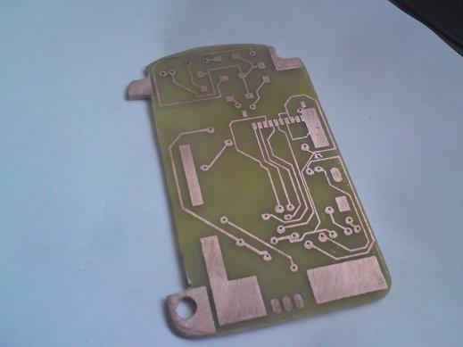
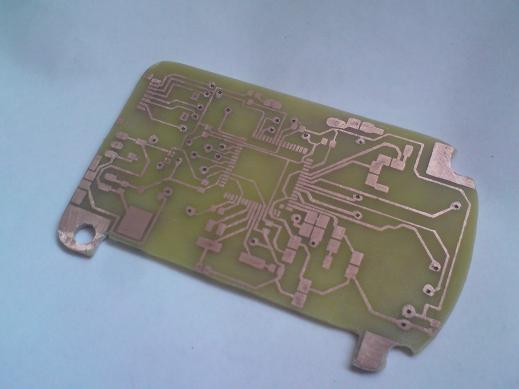
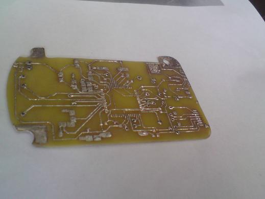
Images:
Video:
Link to original thread --> click here
Last edited: