konrad_3582
Newbie level 4

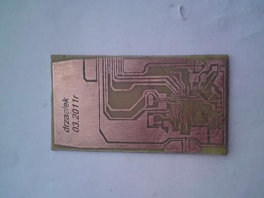
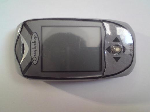
The main goal was to increase the frequency range but maintaining the cheapest cost. Large and inexpensive color display has been used.
Drzasiek wanted build a mobile device, so he was looking for small elements. Finally he used Atmega 32-16AU as the project's base.
Hardware
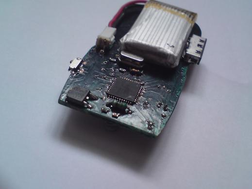
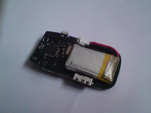
- Atmega 32-16AU with16 MHz clock
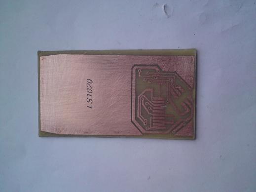
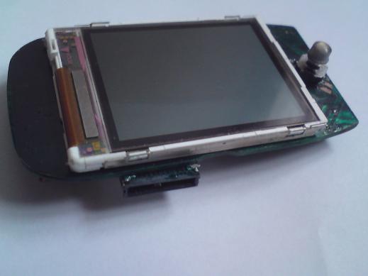
- 176x132 LCD, TFT, 65536 colors, LS020 driver
- A / C converter – built-in ATMega's converter with 1 Mhz clock. Measured sampling rate - 70 kHz approx.
Software Update: 14 April, 2011 - The transmitter clock 2MHz, sampling frequency about 140 KHz
- Handling - Siemens CX65's joystick
- Battery-LI-POL 3,6 V, 500mAh
- Power supply - 3.3 V with linear stabilizer
Software
The whole program has been written in C and compiled by WinAVR. It takes over 3000 lines (31 kB of flash memory). RAM uC is totally used. The code was changed several times to make it optimized.
Display driver was initially remake of Saper_2's driver and at the beginnig he used the display L2F and M128 which he switched to the Kranz's driver and hardware SPI. After changing to the LS020 and the M32 he was practically forced to write driver by himself.
Parameters
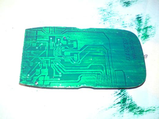
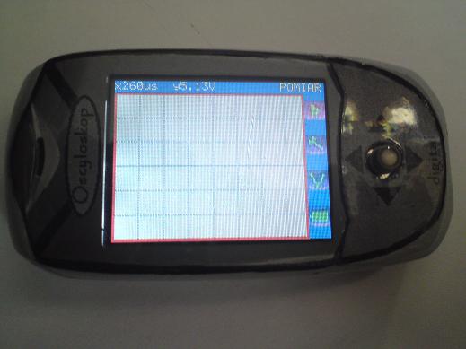
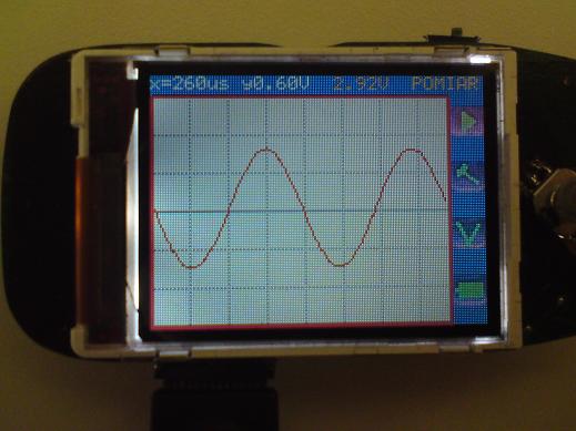
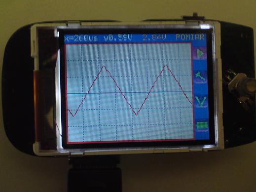
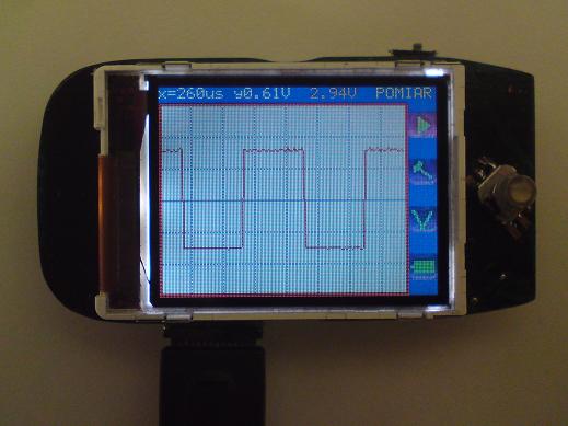
The oscilloscope is designed to measure AC voltages in the range up to 25V and the frequency range up to 10kHz, after updating the software to 15-20 kHz (although you can and more except that the image will be of inferior quality). Working area is the display size of 118x155 pixels, is divided into parcels horizontally and vertically. The top of the bar shows the time to plot X and plot the voltage at the Y. On the right side is a 4-position menu:
1st Starting measurement
2nd Settings
3rd Voltmeter
4th Battery Indicator
Starting the measurement enables the continuous measurement that can stop the movement of the joystick. The course of the display is automatically scaled amplitude is calculated and is shown on the top bar, is calculated plot X and Y and also displayed. The course is synchronized (on the course of the film is unstable due to the instability of the generator on the LM555 and phone charger). In the settings you can change the time base by setting the transducer at which the sample was collected, and conversely, what a pixel is displayed a sample. You can also adjust the gain level, a shift in the vertical axis. It is also possible to choose whether they appear to be the same discrete values, or whether the course is to be interpolated (piecewise). Additionally, it is possible to change gear on the input voltage divider which may prove useful in measuring the needs of larger tensions. You can then make the poll an additional voltage divider and change the transmission settings.
The unit is also equipped with a voltmeter measuring with an accuracy of about 0.03 V.
The final element of the menu is the battery meter. It shows the current battery power supply's battery as standard, plus displays the voltage in Volts.


Link to original thread --> click here
Last edited: