palmeiras
Full Member level 6
- Joined
- Feb 22, 2010
- Messages
- 375
- Helped
- 61
- Reputation
- 122
- Reaction score
- 50
- Trophy points
- 1,308
- Location
- South America
- Activity points
- 4,199
Hi Everybody,
Please, can anyone help me on this issue?
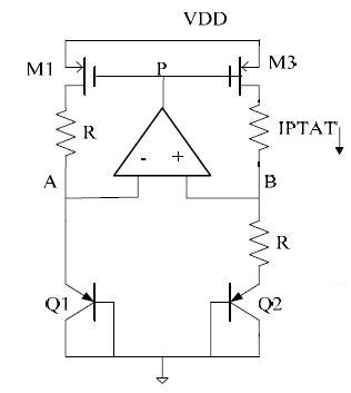
I have designed a traditional Bandgap voltage circuit, shown in figure 1 (VDD = 1.8V). It works properly. However, when I´m doing a DC simulations (Temperature sweep) in cadence, in some cases (for instance, in some corners), it stabilizes at a wrong operating point.
The wrong operating point is: Current IPTAT ~ pA and node_P = high values. The correct operating point is I1 ~ 20 uA and node_P = 1.2 V.
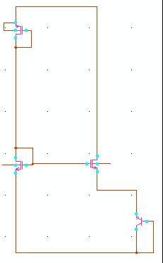
I have tried a start-up circuit, but it doesn’t work well for all cases. It still continues stabilizing at wrong op-point. I do believe that the problem is the start-up circuit. Am I right?
Do you have any suggestion of start-up circuit for this Bandgap topology?
Thank you very much,
Please, can anyone help me on this issue?
I have designed a traditional Bandgap voltage circuit, shown in figure 1 (VDD = 1.8V). It works properly. However, when I´m doing a DC simulations (Temperature sweep) in cadence, in some cases (for instance, in some corners), it stabilizes at a wrong operating point.
The wrong operating point is: Current IPTAT ~ pA and node_P = high values. The correct operating point is I1 ~ 20 uA and node_P = 1.2 V.
I have tried a start-up circuit, but it doesn’t work well for all cases. It still continues stabilizing at wrong op-point. I do believe that the problem is the start-up circuit. Am I right?
Do you have any suggestion of start-up circuit for this Bandgap topology?
Thank you very much,
Last edited: