Continue to Site

Welcome to EDAboard.com

Welcome to our site! EDAboard.com is an international Electronics Discussion Forum focused on EDA software, circuits, schematics, books, theory, papers, asic, pld, 8051, DSP, Network, RF, Analog Design, PCB, Service Manuals... and a whole lot more! To participate you need to register. Registration is free. Click here to register now.

Would this AC voltage sensor circuit work?

Status
Not open for further replies.

yingdea

Newbie level 3
Joined
May 1, 2013
Messages
4
Helped
0
Reputation
0
Reaction score
0
Trophy points
1,281
Location
New York, NY
Activity points
1,313
Hey All,

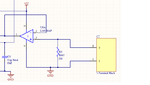
I realized a (potential) problem of my ac voltage sensing circuit, attached below.

the current source at the top left outputs ac current, and passes R5 to convert it to voltage and inputted in to the op-amp U1, whose power supply pin connects to GND. The output waveform I wanted is the top half sine or saturated waveform, and let the negative half get chopped out. The question here is that, would the AC voltage across the R5 affect the GND's voltage potential so that the GND of the U1 is actually not zero all the time, and the output wave form cannot be chopped out as wanted?

Thank you guys in advance for your help. My first post ever here. So hope you can help me out of this one!

Best,


Untitled.png
 

The question here is that, would the AC voltage across the R5 affect the GND's voltage potential
How can a voltage across R5 affect a ground potential? You have to assure that ground is actually the common potential of your circuit, also that the current flows into the resistor.

Regarding intended intended halfwave rectification of single supply OP, that will work, but not perfectly due to LM358 output saturation voltage. Thus it's not suited as a precision rectifier.

There's a similar circuit providing full-wave rectification

 
Thank you very much for your prompt reply, FvM!

In that case, I built a circuit according to following schematic, where CT stands for the output from the AC current transformer and the output waveforms at the output of the voltage follow is attached. From them you can see that when the amplitude of the input(#1, yellow) large enough, the output waveform(#2 in light blue) is distorted. I attributed this phenomenon to the common GND issue, but if it is not that case, what would potentially cause this behavior?

I used a function generator to mimic the output from the CT during the testing.
 

Attachments

  • Untitled1.png
    Untitled1.png
    24.7 KB · Views: 106
  • waveform0.bmp
    146.3 KB · Views: 87
  • waveform1.bmp
    146.3 KB · Views: 112
  • waveform2.bmp
    146.3 KB · Views: 91
  • waveform3.bmp
    146.3 KB · Views: 79

Your new circuit is ignoring the OP maximum input voltage specification. Depending on the input voltage and current, you'll distroy the chip or at lest cause unexpected behaviour. Your first design avoids this problem.
 
  • Like
Reactions: tpetar

    tpetar

    Points: 2
    Helpful Answer Positive Rating
Thank you, as long as the shared GND's potential won't be affected, I can adjust the input current from the CT to make sure it's within the range.
 

yingdea, I can see many issues with your design that make the output sensitive to input level.

The LM358 has no operation within 1.5 to 2V near each supply rail and your design, Vee=ground.
Thus any signal less than 2V above ground is distorted (in your case dead band with inversion).

Fix. Use a split supply, virtual mid V+ reference or a "rail to rail" Op Amp type. :smile:

The second design is no better as a buffer , with a 200 source impedances you can do same as this with a 2V rectifier diode an no op-amp. :-o

If you must use a single supply say so. 8-O

If you must sense low currents, specify the min input V level which is designed by input offset error. :shock:

Assuming this is not AC Line and Neutral , beware of Neutral to ground offset from ground faults and long wires which may coupline stray noise without a filter.
Fix .. Add an EMI filter (small cap ) on Feedback of Op Amp

LPF set at or above max freq.. :p
 
The LM358 has no operation within 1.5 to 2V near each supply rail and your design, Vee=ground.
Thus any signal less than 2V above ground is distorted (in your case dead band with inversion). [/QUOTE

LM358 is a single supply OP. Input common mode voltage includes ground, output voltage swings near to ground, depending on the output current.
 
Thank you very much for your suggestion, the experience you have and just shared is quite beneficial to newbies like me.
 

TY FvM , I forgot and meant below ground.

It can be used a single supply Op Amp, if you meet Vin spec = 0 to V+ -1.2v

The photo posted shows what happens when input goes below ground with output amplified and inverted when input goes 0.6V below ground.
90789d1368037018-waveform1.bmp


You might be able to clamp this with a 0.3V Schottky diode (anode to ground) on the input and make it work below Vee.
But consider the LPF cap feedback for > EEG freq noise.
 
  • Like
Reactions: FvM

    FvM

    Points: 2
    Helpful Answer Positive Rating
Status
Not open for further replies.

Similar threads

Part and Inventory Search

Welcome to EDABoard.com

Sponsor

Back
Top