Vermes
Advanced Member level 4
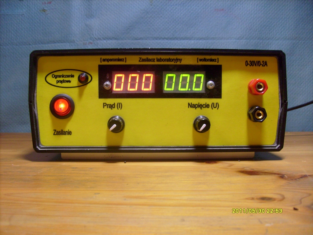
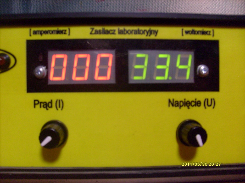
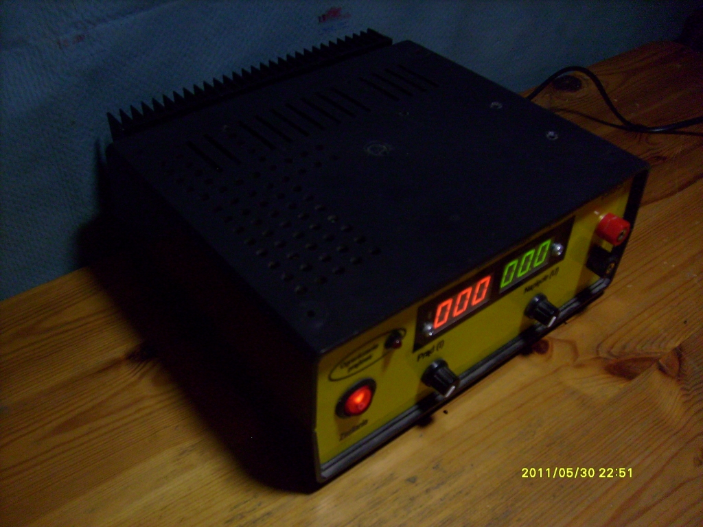
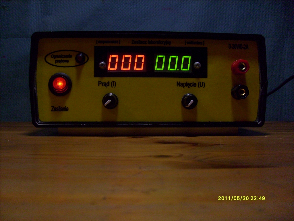
This design is hand-made power supply with continuously adjustable output voltage in the range of 0-30V (0-33.4) and continously adjustable current limitation in the range of 0-2A (0.002-2).
The power supply was based on a well known scheme: LINK.
Changes to the original device:
- decreasing of the current limitation range (to 2 A)
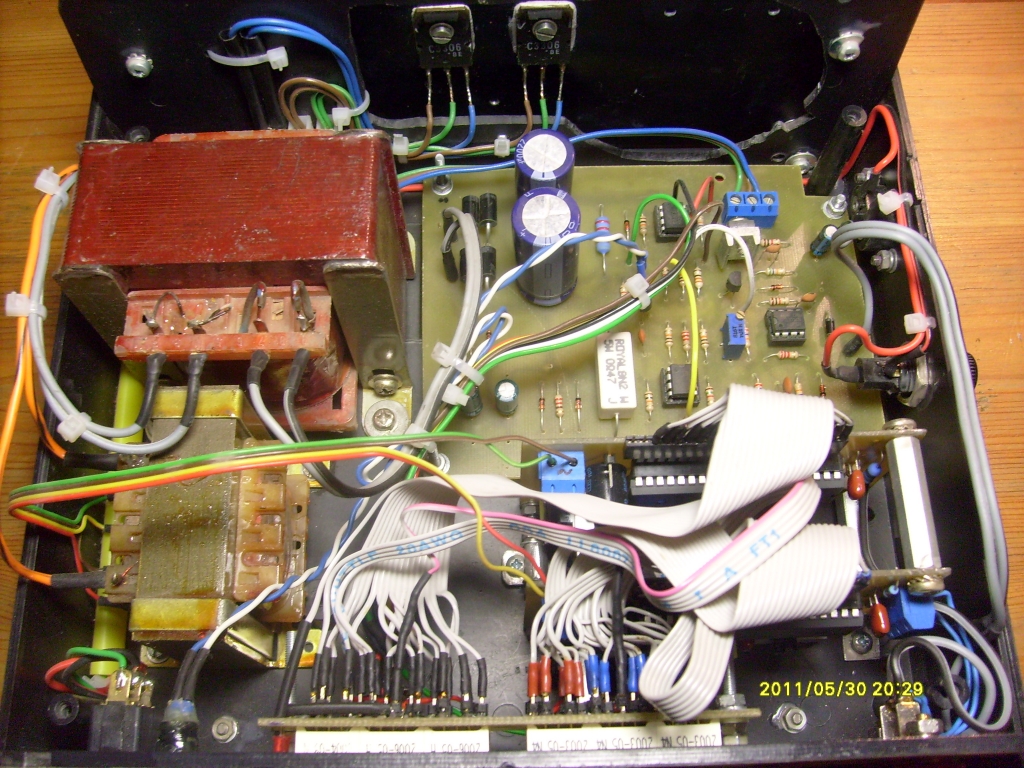
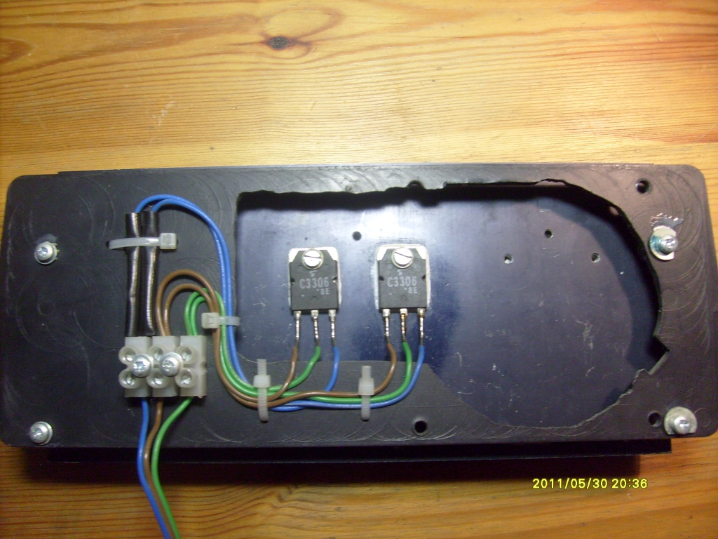
- instead of one final transistor (2N3055) – two power transistors C3306 (from an amplifier)
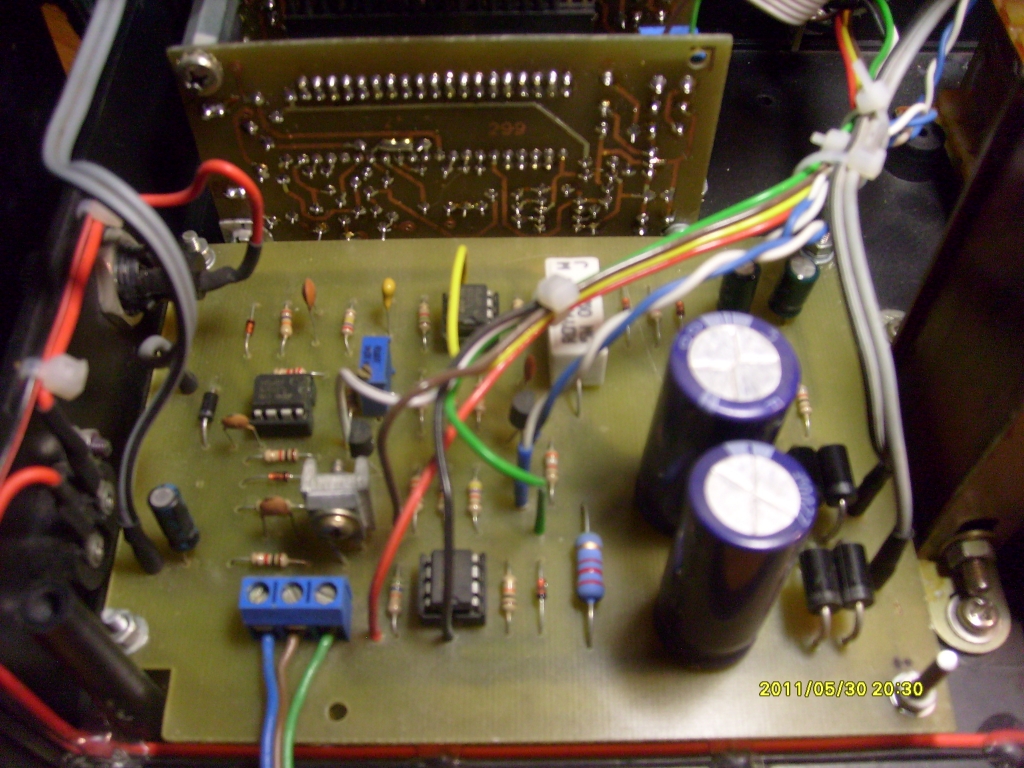
- two emitter resistors added to the transistors
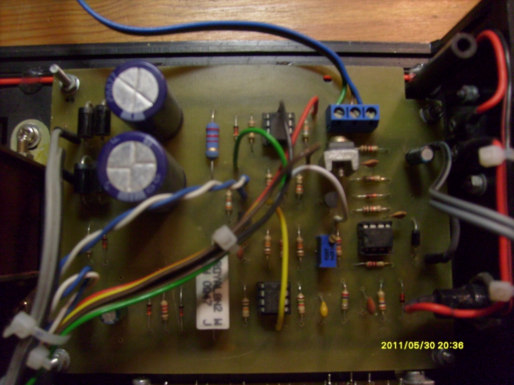
- changes on the main board: Q2 (2N2219) to a popular transistor BD139 and the capacitance of C1 was enlarged from 3300uF to 5500uF
Components:
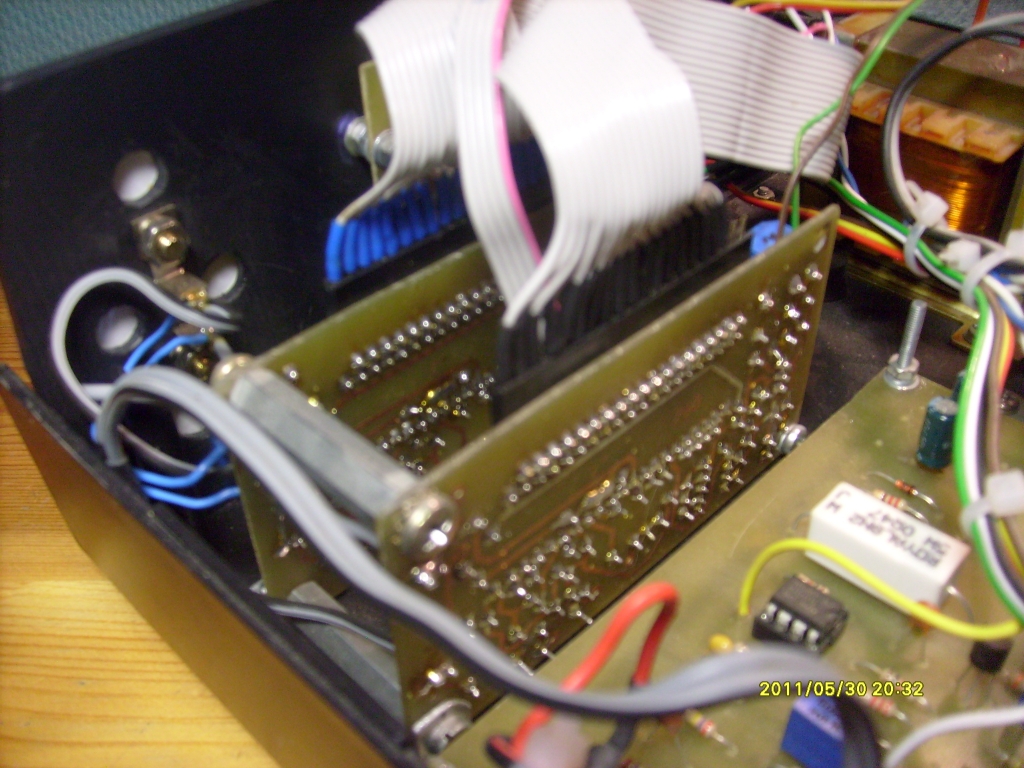
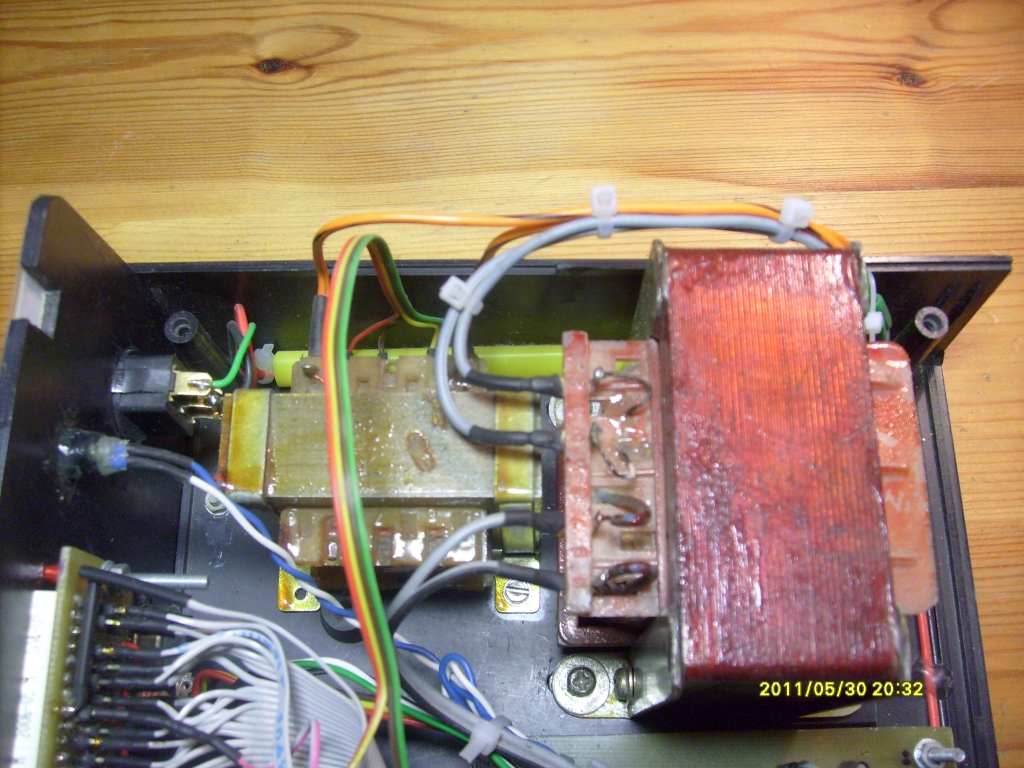
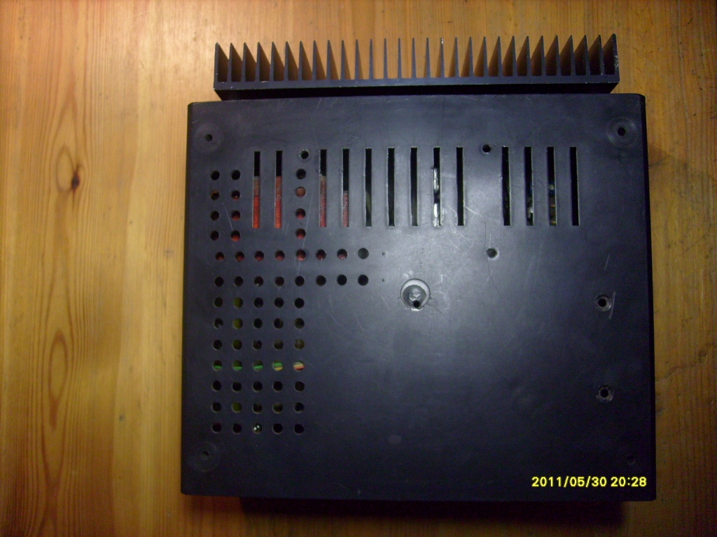
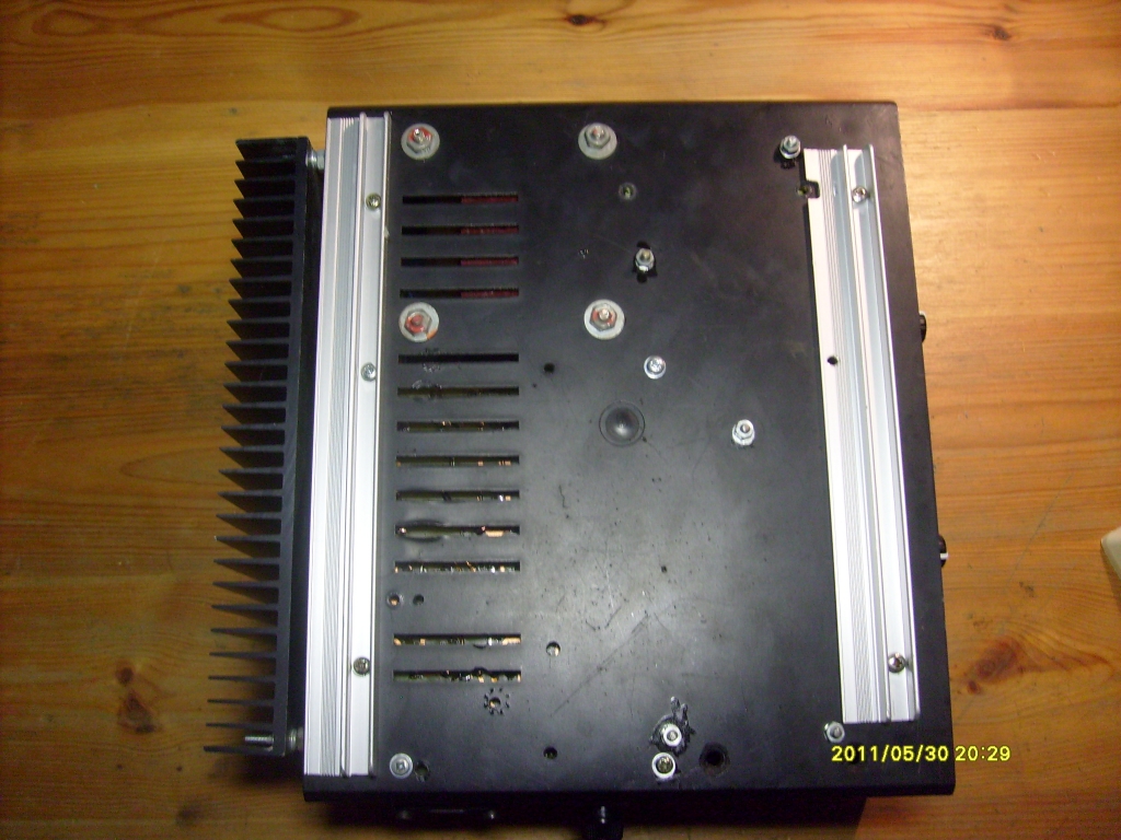
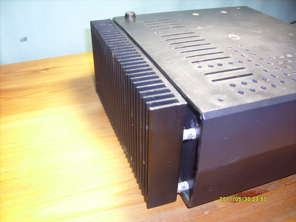
PCBs were printed by thermal transfer method. Housing from a broken rectifier was cleaned and reinforced from the bottom using two aluminum pieces.
Pictures:

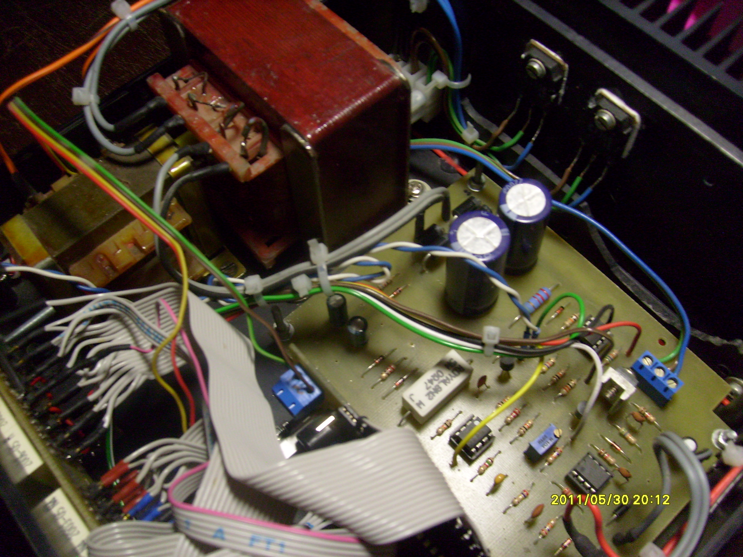
And two pictures in twilight:
Link to original thread (useful attachment) – Zasilacz warsztatowy 0-30V, 0-2A