Continue to Site

Welcome to EDAboard.com

Welcome to our site! EDAboard.com is an international Electronics Discussion Forum focused on EDA software, circuits, schematics, books, theory, papers, asic, pld, 8051, DSP, Network, RF, Analog Design, PCB, Service Manuals... and a whole lot more! To participate you need to register. Registration is free. Click here to register now.

Wireless Power Transfer model

Status
Not open for further replies.

zero_coke

Newbie level 6
Newbie level 6
Joined
Oct 28, 2012
Messages
11
Helped
0
Reputation
0
Reaction score
0
Trophy points
1,281
Visit site
Activity points
1,423
Hello, I have a few questions on the models presented on Wireless Power Transfer by MIT and other various sources seen in IEEE journals

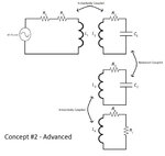
Q1: Can I model a 4 coil system whereby the first two are inductively coupled, the middle two are resonant coupled, and the last two are inductively coupled, using ideal air-core transformer with non-unity coupling coefficient? In Multisim I'm able to couple multiple inductors so as long as I know the primary and secondary inductances as well as mutual coupling coefficients. Can I use this to simulate my 4 coil wireless power setup?

Q2: What is the role of frequency? There are so many variables and I don't know the importance of frequency. The only thing I can think of is the FCC regulations on magnetic field strength (A/m) at different frequencies. It's 2.19 A/m up to 1 MHz, and then 2.19/f (MHz) after that which allows you less field strength at higher frequencies which I don't understand why. Also, another thing I found was that you must remain in near-field which is 0 to lambda / 4 distance. Do I even need to consider this because I'm not doing the same setup as MIT where they use self-resonant coils, I'm using LC resonant coils with lumped elements. Do I need to worry about H field strength limitation posed by FCC?

Q3: How is impedance transformation done in 4 coil resonant & inductive system? I mean, how can I transfer the load impedance from my 4th coil all the way into my 1st coil? I cannot use regular transformer ratio transformation because these are non-ideal transformers and I don't know how to do it.

The two concepts are attached as images and the journal I'm using as a reference is too. It's all explained in the journal but I don't understand maybe I'm lacking enough knowledge on circuits and AC analysis. I need to know how going from concept #1 to concept #2 improves the efficiency in the system. The only thing I can think of is, in order to achieve maximum power transfer, I should introduce 2 new coils so that when you refer the impedances to the primary you will have a closer match to the source impedance and thus more power delivered to the driving coil. Is this correct?

Thanks!
 

Attachments

  • concept1.jpg
    concept1.jpg
    32.7 KB · Views: 81
  • concept2.jpg
    concept2.jpg
    50.8 KB · Views: 87
  • hybrid_wirelessPT.pdf
    492.6 KB · Views: 87

having read the article, it does not make clear why the additional coils are required. It must be noted that the input coil is none resonant and it does not seem to be matched to the signal sources output impedance. The only thing I can guess at is that the second coil "gathers" the field from the input coil and concentrates the field around it. This effect is then reproduced by the second resonant circuit. It must be noted that each tuned circuit will have its own loss, so it there must be some "field" effect which is beneficial, but not explained . I would have an attempt to re-design it by pulling a figure out of the air for the impedance reflected by the output circuit back to the input circuit, say 1000 ohms, this is coupled in via some mutual inductance with a lowish coupling factor, say .1. So the input coil and its capacitors are designed for a maximum power transfer into this load. Then go to the output circuit and using the previously calculated mutual inductance adjust the capacitors to achieve resonance/power matching to the load.
For maximum power transfer, you need high Q components with a working Q of 1. i.e. the best system would be a transformer, but at a low coupling factor, there will be a great deal of leakage inductance and the circuits are trying to tune out the mutual inductance.
The lower the frequency, the lower the stray field will be so less interference to other users of this frequency. But the lower the frequency, the bigger the coil will be and its likely that its Q will be lower. At the other extreme, using 30 MHZ the diodes used to rectify the AC are likely to be lower in power rating and more expensive. Likewise it is easier to generate power at lower frequencies, but not by much!!
Frank
 
Hmm thanks for the info. I still need more information as to why the 4 coil system is used and how I could refer the impedances back and forth in non-ideal 4 coil system. Any ideas?
 

I think you are reading more into the multiple coils setup than actually claimed by the authors of the paper. The abstract is telling about the objective, investigate the mutual affectation of multiple wireless energy receivers, particularly resonance frequency shifts. The same happens with multiple RFID cards close together, why the indivual coil resonance is pretuned considerably above the nominal frequency.

My suggestion for realistic simulations of air coil configurations is an AC-magnetic simulator like FastHenry to determine coupling and losses and then put the results into a standard circuit simulator.
 

Yes thanks. I will look into FastHenry and see if it can give me the coupling and losses between these 4 coils.

See, here's my problem:

In a 4 coil system, there are six different interactions going on: 1st & 2nd, 1st & 3rd, 1st & 4th, 2nd & 3rd, 2nd & 4th, 3rd & 4th coils. Now, the system is comprised of 4 coils, of which 2 are in resonant and 2 are inductively coupled. The two that are inductively coupled will nevertheless have low coupling since there is no core, and there is no core because the secondary winding is to be in resonant which must let the flux out so the 3rd coil can pick it up (see the images I attached).

However, my question is: Can I use the coupling coefficient only and vary it (say, in Multisim which allows me to couple multiple coils via coupling coefficients I can assign to them) and model this non-ideal multi-transformer system like so? Can I model a non-ideal transformer in this sense using non-unity coupling coefficients or is there more to it than that? In my opinion, when you have an air core transformer, the only thing you have to worry about is the leakage flux since there is no core losses. Now, can I model this leakage flux via the coupling coefficient or are they totally independent? I modeled each pair of coils in the 4 coil setup as a transformer with non-unity coupling coefficient. Is this an accurate representation of such a model (neverminding the i^2*R losses of the inductors itself)?
 

The coupling of all involved coils can be best represented by a matrix of mutual inductances and losses.

The equation for a single element has the form Vij = Ii *(jwLij + Rij)

FastHenry is showing it in a visual way and can also generate an equivalent SPICE circuit (for a single frequency). Mutual inductances and coupling coefficients can be converted into each other. But there's no equivalent SPICE component for the coupled losses, they have to be modelled by controlled sources.

Although there are no core losses, skin and proximity effect are considerably affecting the efficiency of wireless power transfer.
 

Hi FvM,

So I solved the matrix of equations that relate all the voltages and currents in all 4 coils I have setup (also like how the paper I attached to my original post has it setup too) and all I get is a graph that depicts what I already know: That is, at the resonant frequency I expect the highest power received at the load. I don't know why I'm doing this, I mean, I already know that at resonant frequency I will achieve the highest transfer of power. My question is, to do this, I had to guess the coupling coefficients and I'm sure they are severely inaccurate, and I was wondering how I could measure the coupling coefficients of my coils in real life when I build them? How can I measure the coupling coefficient of two air core coils? I need to know this to get my mutual inductance between them since Mij = k*sqrt(Li*Lj) and only then can I represent an accurate depiction of my system in my matrix simulation so I know how much power I'm dealing with. Right now I'm getting terrible results, some like -20 dB at the load which is pretty bad.

This is what I'm getting on the simulation:

four_coil.jpg

I should mention my parameters:

Vs = 10 V
Rs = 50 ohms
RL = 50 ohms

N1 = N4 = 1 turn each
N2 = N3 = 10 turns each

%Coupling Coefficients
k12 =0.5;
k13 =0.001;
k14 =0.001;
k23 =0.8;
k24 =0.001;
k34 =0.5;
 
Last edited:

The coupling coefficients can be measured according to the definition of mutual inductance: Inject a current into one coil, measure the induced voltage at the others. Or measure Sij with a VNA and transform to inductances.
 

Status
Not open for further replies.

Similar threads

Part and Inventory Search

Welcome to EDABoard.com

Sponsor

Back
Top