Continue to Site

Welcome to EDAboard.com

Welcome to our site! EDAboard.com is an international Electronics Discussion Forum focused on EDA software, circuits, schematics, books, theory, papers, asic, pld, 8051, DSP, Network, RF, Analog Design, PCB, Service Manuals... and a whole lot more! To participate you need to register. Registration is free. Click here to register now.

Wide Swing cascode Doubt - please explain

Status
Not open for further replies.

gmajay123

Newbie level 6
Joined
Oct 24, 2008
Messages
12
Helped
2
Reputation
4
Reaction score
1
Trophy points
1,283
Activity points
1,361
Wide Swing cascode Doubt

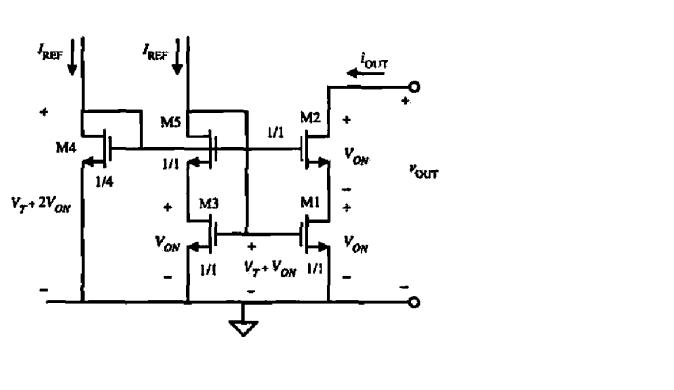
What i know is both the rail devices should see the same drain voltage for better matching. But Why is the gate of M3 tied to Drain of M5.


Re: Wide Swing cascode Doubt

Hi gmajay123,

It is not clear from the schematic you supplied what the purpose of this circuit is, what is more confusing is that both the currents at the left are labelled Iref ie: not "Iref1" and "Iref2". However, I suspect that this circuit is a means of getting Iout (drain current of M2) to be equal to Iref into M5 under wide variations of Vout, ie: a current mirror. In this circuit, M1 and M3 form the mirror, while M2 protects M1 from variations in Vds, thus making this a more accurate current mirror (M2 "cascodes" M1)

To answer the question, why is gate of M1 and M3 tied to drain of M5: well, if you look at the circuit with M5 removed, then it is just a current mirror with a cascode on M1 and M4 setting up the bias for M2. M1 and M3 would need some bias also. That is where M5 comes into play; it will find its operating point according to the current being driven into its drain, and it will set its Vgs (actually, Vdg) accordingly, in conjunction with operation of M3. Just think of Iref (into M5) increasing or decreasing by a little bit, and you will see how the voltages of M5 and M3 interact.

Hope this helps.
 

Wide Swing cascode Doubt

It is probably easier to look at the progression of the design from a "simple" cascode without M5. Then you have M3 gate connected to it's own drain to form a mirror. (See pages 643/644 of the R. Jacob Baker book CMOS Circuit Design Layout & Simulation 2nd edition if you have it.)

M4 is made "long" so it holds the source of M2 above Vss. This is then a cascode which can go quite close to Vss. However, while the output is quite good, M3 current will not match M1 because the drain voltages will be quite different. So, M5 is added to M3 to hold the drain of M3 at the same voltage as M1 so the mirror is closer to 1:1.

I hope that makes sense! The books probably do a better job of explaining it.

Keith.
 

    gmajay123

    Points: 2
    Helpful Answer Positive Rating
Hi,

Well, that is a cascode current mirror. This topology is implemented in order to eliminate the accuracy-headroom trade-off presented in traditional cascode current mirror. M1 and M2 consumes minimum headroom. You can study this circuit in this book: "Design of Analog CMOS Integrated Circuits" by Razavi (chapter 5).

Best Regards,
 

Status
Not open for further replies.

Similar threads

Part and Inventory Search

Welcome to EDABoard.com

Sponsor

Back
Top