Continue to Site

Welcome to EDAboard.com

Welcome to our site! EDAboard.com is an international Electronics Discussion Forum focused on EDA software, circuits, schematics, books, theory, papers, asic, pld, 8051, DSP, Network, RF, Analog Design, PCB, Service Manuals... and a whole lot more! To participate you need to register. Registration is free. Click here to register now.

Why Ganged Capacitors?

Status
Not open for further replies.

Maximzodal

Newbie level 3
Joined
Jul 10, 2013
Messages
3
Helped
1
Reputation
2
Reaction score
1
Trophy points
3
Activity points
38
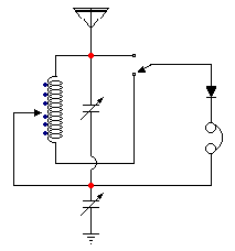
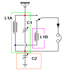
First of all, I know enough electronics to be dangerous but I'm very willing to learn. I appreciate your patience. I recently decided to build a "better" crystal radio than the oatmeal box set I made as a kid. There are a lot plans! But many use 2 or 3 or 4 gang variable capacitors with various pF units. I understand how a variable capacitor works in an L/C circuit to 'tune' the resonant frequency, but why 2 or more gangs? What do they bring to the project? Are they connected to the same L/C circuit? I did a search here and on google but if the information is available I haven't been able to find it. Can anyone point me in the direction where I can be educated?

Thanks,
Max
 

There are many applications of ganged capacitors. Many of them used in circuits that now became obsolete. May be you can post a link to the specific circuit.
For example. Ganged capacitors were used in am and fm radios. One section of the capacitor is used to tune the RF input circuit and the other to set the local oscillator frequency. More advanced receivers used 2 sections to tune the RF input by using a 3 ganged capacitor. In this way you track the input filter to the local oscillator.
Other applications require special capacitor configurations driven by the same shaft. As the "split-stator" and "differential" types. Where the capacitance of one section may increase while the other decreases as you turn the shaft.
 
There are many applications of ganged capacitors. Many of them used in circuits that now became obsolete. May be you can post a link to the specific circuit.

For example. Ganged capacitors were used in am and fm radios. One section of the capacitor is used to tune the RF input circuit and the other to set the local oscillator frequency. More advanced receivers used 2 sections to tune the RF input by using a 3 ganged capacitor. In this way you track the input filter to the local oscillator.
Other applications require special capacitor configurations driven by the same shaft. As the "split-stator" and "differential" types. Where the capacitance of one section may increase while the other decreases as you turn the shaft.

Thanks for your prompt reply. The simplest example is at https://tinyurl.com/mzdrsza for the MRL #2 Crystal Radio kit. If I'm reading the circuit correctly, it looks like the two variable capacitors are connected in series. If they are the more common 365 pf then it appears to me the total capacitance would be 182.5? I'm just not understanding what two separate variable caps in series brings to the table?

And perhaps the example, The Tuggle Two crystal radio, at https://crystalradio.net/crystalsets/miketuggle/
is doing the same thing? I can understand that upper VCs are involved in the L/C circuit but I can't figure out what lower one's do?

Thanks again,
Max
 
https://tinyurl.com/mzdrsza for the MRL #2 Crystal Radio kit. If I'm reading the circuit correctly, it looks like the two variable capacitors are connected in series. If they are the more common 365 pf then it appears to me the total capacitance would be 182.5? I'm just not understanding what two separate variable caps in series brings to the table?

And perhaps the example, The Tuggle Two crystal radio, at https://crystalradio.net/crystalsets/miketuggle/
is doing the same thing? I can understand that upper VCs are involved in the L/C circuit but I can't figure out what lower one's do?
[/QUOTE]

Hi Max,

in MRL #2 circuit the capacitors aren't actually ganged - no dotted line connecting them, + look at the photos on the w/site; you can see there are 2 separate capacitors.

Also, they aren't simply in series - I've redrawn the circuit to show more clearly what's happening. In the original diagram it's not altogether clear that C1 (ie the upper capacitor is connected to both the top of the coil and the aerial), and that C2 (the lower) is connected to the headphones and the coil tap. I've put red dots on the diagram to indicate this. The blue dots on the coil L1(AB) are the taps - look at the photos again you can see a fairly crude switch on the front panel and the wire to the taps in the rear view.

Look at diag.2 - L1A and C1 form the main tuned circuit, the portion of L1 selected by the switch ie L1B acts as rf coupling to the diode. C2 determines the coupling between the tuned circuit and earth. It could easily be moved to be in series with the aerial and perform the same function.

Does that help?

Re the Tuggle circuit - you probably worked out that C1a is the same as C1 and C1b performs the same function as C2.

1544063900_1376611460.png

8927708400_1376611573.png
 
Look at diag.2 - L1A and C1 form the main tuned circuit, the portion of L1 selected by the switch ie L1B acts as rf coupling to the diode. C2 determines the coupling between the tuned circuit and earth. It could easily be moved to be in series with the aerial and perform the same function.
Antenna impedance is dependent on frequency. For a specific length of antenna, its impedance get matched with free space at a particular frequency only.
To get best result, antenna impedance needs to be tuned to match with free space at all radio stations.
I guess C2 is used to tune the antenna impedance.
 

Hi Max,

in MRL #2 circuit the capacitors aren't actually ganged - no dotted line connecting them, + look at the photos on the w/site; you can see there are 2 separate capacitors.

Also, they aren't simply in series - I've redrawn the circuit to show more clearly what's happening. In the original diagram it's not altogether clear that C1 (ie the upper capacitor is connected to both the top of the coil and the aerial), and that C2 (the lower) is connected to the headphones and the coil tap. I've put red dots on the diagram to indicate this. The blue dots on the coil L1(AB) are the taps - look at the photos again you can see a fairly crude switch on the front panel and the wire to the taps in the rear view.

Look at diag.2 - L1A and C1 form the main tuned circuit, the portion of L1 selected by the switch ie L1B acts as rf coupling to the diode. C2 determines the coupling between the tuned circuit and earth. It could easily be moved to be in series with the aerial and perform the same function.

Does that help?

Re the Tuggle circuit - you probably worked out that C1a is the same as C1 and C1b performs the same function as C2.

1544063900_1376611460.png

8927708400_1376611573.png
[/QUOTE]


Thanks for taking the time to help me. Your explanations are helpful. Your wire crossing symbol is what I was accustomed to.

OK, I think you are saying that the ganged variable caps in the Tuggle circuit are like separate C1 and C2 in the other circuits? I guess I thought those caps would have to be adjusted differently.

Thanks again,
Max
 

Status
Not open for further replies.

Similar threads

Part and Inventory Search

Welcome to EDABoard.com

Sponsor

Back
Top