JohnJohn20
Advanced Member level 4

- Joined
- Feb 2, 2012
- Messages
- 111
- Helped
- 0
- Reputation
- 0
- Reaction score
- 0
- Trophy points
- 1,296
- Activity points
- 2,377
Hi.
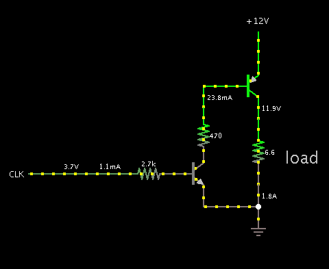
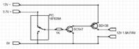
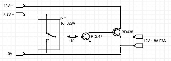
I want to use a PIC running on 3.7V to switch a 12V supply (where both power supplies have a common 0V).
I was using the PIC to control a TIP 120 but could only switch the negative line.
So I tried using the PIC to control a npn transistor (BC547) to drive a PNP power transistor (BD438) as shown in in the attached diagram.
But this doesn't work. Why?
- - - Updated - - -
Actually guys. It works fine. I had the BD438 connected up wrong. Sigh.