Continue to Site

Welcome to EDAboard.com

Welcome to our site! EDAboard.com is an international Electronics Discussion Forum focused on EDA software, circuits, schematics, books, theory, papers, asic, pld, 8051, DSP, Network, RF, Analog Design, PCB, Service Manuals... and a whole lot more! To participate you need to register. Registration is free. Click here to register now.

Why 33pf & 10pf capacitor suggested for RF application ?

HardwareGeek

Newbie
Joined
Feb 16, 2023
Messages
1
Helped
0
Reputation
0
Reaction score
0
Trophy points
1
Activity points
20
Hi All,

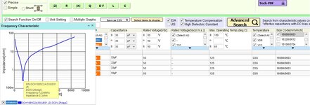
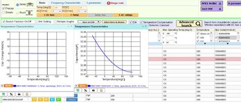
I am designing a board based on GPS and LTE modules. I have read many Google threads for HW design guidelines, and I found many have suggested using a 33 pF capacitor to eliminate noise from GSM 900 MHz, while a 10 pF capacitor could eliminate noise from the DCS 1800 MHz frequency on power pins and other near-by semiconductor ICs (audio). I had tried to find the theoretical calculation behind it but didn't have success. Can anyone help me understand the reason behind this specific value?

By using Xc = 1 / (2πfC), at 900 MHz, 33 pf has a lower impedance (5Ω), effectively acting as a short circuit for high-frequency noise. But why 33 pf, not 22 pf or any other value?
 
Capacitors don not eliminate the Noise, there is no such rule.
They are used to match, de-coupling, coupling or inductive compensation purposes.
 
a 33 pF capacitor to eliminate noise from GSM 900 MHz,

This statement was valid 20+ years ago, when the chosen size of SMD components used in GSM mobile phones, was 0603. At that time a 33pF size 0603 had the SRF about 900MHz. But not anymore. First, because the technology today improves a lot and the SRF of a 33pF 0603 cap is greater, about 1200MHz.
On second place, today, the SMD size used in mobile phones is 0201 or even 01005, which both have much greater SRF.
 

Attachments

  • 0603.jpg
    0603.jpg
    112.6 KB · Views: 43
What do you do if your RF module is multi band rather than single frequency? Most likely it is. The arbitrary suggestion of 10 or 33 pF won't work then.

You want low impedance, non-resonant power supply and control signal filters in the first place. Resonant traps are a last resort if circuit inductance is too high. Unfortunately the 10 pF may work on one board but fail on the other due to layout differences.
 
For SMD capacitors made with nowadays technology, the SRF frequency location is stable with temperature. There are many manufacturers that depends their RF circuit designs on SRF properties, especially of capacitors. Myself I did this many times including evaluation of caps SRF vs temperature.
Overall, using SRF properties, is like you get a free filtering.
 

Attachments

  • temp.jpg
    temp.jpg
    160.5 KB · Views: 45
It is well known that 10 and 33 pF are common microwave low ESR caps in the High Q type C0G type caps.
The reason is that this material is chosen is that it has higher self-resonant frequencies (SRF) than other types and also is low Dk limiting the size in pF for small SMD packages and also the C0G/NP0 are the lowest temperature coefficient stable capacitors. +/-50 ppm/'C while there are other common types that have +100 ppm/'C to -500 ppm/'C. There are std MLCC XR7's that are also rated as low ESR but are far less stable and far lower SRF unsuitable for microwave > 1GHz.

There are other variables that affect high SRF and low ESR, but High-Q C0G types are dominant.

This 33 pF is suitable for 928 MHz while 10 pF is suitable for <= 2.5 GHz.

e.g.
1698119997820.png
 

LaTeX Commands Quick-Menu:

Part and Inventory Search

Welcome to EDABoard.com

Sponsor

Back
Top