Continue to Site

Welcome to EDAboard.com

Welcome to our site! EDAboard.com is an international Electronics Discussion Forum focused on EDA software, circuits, schematics, books, theory, papers, asic, pld, 8051, DSP, Network, RF, Analog Design, PCB, Service Manuals... and a whole lot more! To participate you need to register. Registration is free. Click here to register now.

[SOLVED] which one to choose, a capacitor or DC block?

Status
Not open for further replies.

eigenroot

Junior Member level 3
Joined
Feb 1, 2011
Messages
30
Helped
0
Reputation
0
Reaction score
0
Trophy points
1,286
Activity points
1,557
I need to amplify a time dependent signal which has a large DC background (at least 100 times larger than the signal amplitude). So I think I need something to filter out the DC background. A big capacitor can do this. But at the same time I also see something called DC block. I notice that most DC blocks have higher high cutoff frequency (tens of GHz) than I need, because the bandwidth of my signal is 10MHz at most. However, the low cutoff frequency of these DC blocks is also higher generally (~10kHz). In my case, I need the low cutoff frequency to be lower, preferably smaller than 1kHz.

I am just wondering which one is the right animal for my situation, a large capacitor (maybe hundreds of uF?), or a DC block with very low cutoff frequency? I kinda see that DC blocks have nicer performance in high frequency part, but are they good for my case?
 
Last edited:
whats a "uC"?
Does the DC value change, or is it constant?
what is your AC load impedance?
 
Last edited:

whats a "uC"?
Does the DC value change, or is it constant?
what is your AC load impedance?

Sorry, it should be "uF" not "uC". I have corrected the typo in the post.

The DC value is supposed to be constant, although in real life there may be some drift in a time scale that is much longer than the measurement time.

There should be 50 Ohm source impedance to the amplifier, and the amplifier drives either 50 Ohm or 1M Ohm load.
 

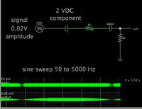
Not sure if this matches your configuration...

A .68 uF capacitor provides noticeable reduction at 1000 Hz. This is based on 100 ohms effective resistance, if I get the correct idea there is 50 ohms on each side of it.

Screenshot of my simulation:


The incoming signal sweeps from 50 Hz to 5 kHz, to demonstrate the rolloff curve.

I used a signal of 0.2V amplitude, and a DC component of 2V which is 100 x larger (as you state).

The snapshot is at 1 kHz. Notice the scope trace shows the output is much less compared to when the frequency is 4 or 5 kHz.

With the 1M ohm as the next stage, you can use about 200 pF value. The 1M impedance will barely load the incoming signal.
 
Well, if the DC is always there, a simple series cap will do it.

However, if the DC voltage comes and goes, you can have trouble. Lets say, for example, that the DC voltage goes from 0 to 24 VDC when you turn on the system, and you are trying to see a 100 mV AC signal. At startup, you will get a 24 V positive spike into your amplifier. At turn off, you will get a -24 V spike going into your amplifier. So...the key to this is to make a circuit that will not blow up your amplifier!

I would suggest brad's circuit, but with antiparallel diodes (schottky if the ac voltage is small, junciton or zener diodes if the AC voltage is big) connected from the amp input to ground. I would also put a 1K resistor to ground there to "bleed off" any charge ending up on the capacitor.

If you have a fast switching DC background voltage, there are more complicated "DC Restoration Circuits" that can be used.
 
Not sure if this matches your configuration...

A .68 uF capacitor provides noticeable reduction at 1000 Hz. This is based on 100 ohms effective resistance, if I get the correct idea there is 50 ohms on each side of it.

Screenshot of my simulation:


The incoming signal sweeps from 50 Hz to 5 kHz, to demonstrate the rolloff curve.

I used a signal of 0.2V amplitude, and a DC component of 2V which is 100 x larger (as you state).

The snapshot is at 1 kHz. Notice the scope trace shows the output is much less compared to when the frequency is 4 or 5 kHz.

With the 1M ohm as the next stage, you can use about 200 pF value. The 1M impedance will barely load the incoming signal.

Thanks for your detailed reply. Yes, it seems that a decoupling capacitor will do the work.

Now I need to get such a capacitor. It needs to be low-noise and low leakage, since the AC signal is very small (only tens of uV). Do you have any suggestion? Thanks.
 

As you may know, electrolytics have a reputation for being noisy.

According to an article about tests on different capacitor types (by Walter G. Jung and Richard Marsh):

"Up to values of about 10,000 pF, polystyrene is the best all around choice, as it has reasonable size and is readily available in many sizes, with tight tolerances available. Above 10,000 pF, and up to 0.1 u F, it still can be used but is much harder to obtain.

Above, 0.1- u F polypropylene (or metalized polypropylene) is the dielectric of choice, as it has nearly the same relative qualities of DF and DA as polystyrene. Tight tolerances are available (but will be special order), and you can get capacitors up to 10 u F or more."

**broken link removed**
 
Status
Not open for further replies.

Part and Inventory Search

Welcome to EDABoard.com

Sponsor

Back
Top