Continue to Site

Welcome to EDAboard.com

Welcome to our site! EDAboard.com is an international Electronics Discussion Forum focused on EDA software, circuits, schematics, books, theory, papers, asic, pld, 8051, DSP, Network, RF, Analog Design, PCB, Service Manuals... and a whole lot more! To participate you need to register. Registration is free. Click here to register now.

Which is better Configuration for Power Supply ?

Status
Not open for further replies.

asking

Full Member level 5
Joined
Sep 21, 2010
Messages
279
Helped
6
Reputation
12
Reaction score
6
Trophy points
1,298
Activity points
3,377
Which is better Transistor Configuration for Power Supply ?

Hello,

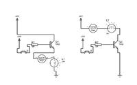
I have shown the image with two different configuration... Please guide me which would be better combination ? Is there any chance of reducing heat by changing configuration ? As Collector region is bigger than emitter so which of the design is better ? Does it matter ? which design i should consider or both of them are same ? M little bit confused...


With the first circuit, there will be .8V dropped across transistor, in the second, .2V. You notice this by the slightly lower current in the first figure. The second figure will have 1/4 of the dissipation of the First ( 1 = 2 A X.8V = 1.6W, 2 = 2A X .2V = .4W).
Frank
 

With the first circuit, there will be .8V dropped across transistor, in the second, .2V. You notice this by the slightly lower current in the first figure. The second figure will have 1/4 of the dissipation of the First ( 1 = 2 A X.8V = 1.6W, 2 = 2A X .2V = .4W).
Frank

Thanks mate....for your information...

- - - Updated - - -

So 1st figure is common emitter configuration and 2nd figure is common collector circuit right ?
 

So 1st figure is common emitter configuration and 2nd figure is common collector circuit right ?
No actually reverse is true.

- - - Updated - - -

I think first circuit is better than later. In the second circuit you do not get any gain, because base current is already very high ~2A (~loss), while first circuit carries only collector current and base current is minimum.
First circuit shall dissipate less power.
 

I think that you can increase the base resistor to reduce the base current in the second circuit.
The same can be said of the first circuit also.
 

Re: Which is better Transistor Configuration for Power Supply ?

the second one designe is suitable and 99.9% designer use it .
in second designe transistor is using as switch.


i sugess you that if you are going to use transistor as switch and controlling larg current then EMOSFET is best choice.
 

ohh k guy....can anyone tell me how much minimum current i should provide to transistor base for its full conduction state... i mean fully on.... ? which factor i should look into datasheet ?
 

Find out the BETA of the transistor from spec, Find the wattage of the bulb (decide how much current you want in bulb).
Ib=Ic/BETA. YOu know the base current, decide the base resistance accordingly.
 

ok thanks...will calculate it...

- - - Updated - - -

But do you think....applying excess current to base can also be factor for more heat produced ?
 

There is maybe also a safety aspect to consider as well. The high side switch is prefered because in case of a failure (e.g. the 24V wire breaks or is shorted to ground) it will most likely damage the driving transistor, but not the total 24V power supply.

Enjoy your design work!
 

Status
Not open for further replies.

Part and Inventory Search

Welcome to EDABoard.com

Sponsor

Back
Top