Continue to Site

Welcome to EDAboard.com

Welcome to our site! EDAboard.com is an international Electronics Discussion Forum focused on EDA software, circuits, schematics, books, theory, papers, asic, pld, 8051, DSP, Network, RF, Analog Design, PCB, Service Manuals... and a whole lot more! To participate you need to register. Registration is free. Click here to register now.

Which inductor for which job? Spiral, Conventional or Mline inductor?

Status
Not open for further replies.

f_t

Member level 4
Member level 4
Joined
Jun 30, 2014
Messages
75
Helped
1
Reputation
2
Reaction score
1
Trophy points
8
Visit site
Activity points
633
Friends,
Could you please tell me in what situation I should use which kind of inductors? I mean as you see in the photo, the first one is a conventional inductor, the second one is a Mline, and the third one is spiral (My circuit is not a Ic and is a discrete circuit).
To supply drain of a power amplifier (which passes high current) I should use a conventional inductor or a RF choke or Mline (2.3 Ghz working frequency)?
What about in a matching or filter network which work at 2.3 GHz?
when should I use a spiral one? I think when there is no high current which wants to pass through the inductor, but what about its frequency? low or high?
Thanks

1.jpg
 

The advantage of SMD elements is that you can have large inductance in a small package. For small inductance values, they also have reasonable Q factor and reasonable series resistance.

"Printed" spiral inductors on PCB can take a lot of PCB space, so the useful value range is limited. They are used to simplify component placement and save cost, if the required value gives reasonable physical dimensions. Q factor can be quite good, if you make it physically large.

Transmission lines are distributed elements with series L and shunt C, and don't behave strictly like an inductor because the frequency dependence is different. However, for narrow band use, they can be used to approximate an inductor. Physically, that layout is even larger than a printed spiral inductor, so it is limited to small values (a few nH).

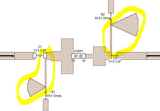
For bias feed in narrow band circuits, the usual approach is to use a narrow lambda/4 line with a radial stub at the end. Radial stub => RF short, transformed by a lambda/4 line => RF open. This is not physically small, but gives good RF blocking of the DC path with (ideally) no capacitive loading of your RF circuit.

Your answer is so helpful. Could you please show me an image of putting lambda/4 line and radial stub in the formation you have proposed?
 

Could you please show me an image of putting lambda/4 line and radial stub in the formation you have proposed?

3315037700_1407576153.jpg


In your case, you would NOT have the series resistor shown in the screenshot
 
  • Like
Reactions: f_t

    f_t

    Points: 2
    Helpful Answer Positive Rating
Spiral inductor can be made very small, I had designed that, but its IPR belongs to Nokia.
 
  • Like
Reactions: f_t

    f_t

    Points: 2
    Helpful Answer Positive Rating
Spiral inductor can be made very small

Yes, if you need small inductance values. Inductance is a function of number of turns and diameter [1]. SMD inductors can stack many turns around an air core or ferrite core, and that enables a wider range of inductance values. For planar ("printed") spirals, we cannot stack turns in 3 dimensions, and we cannot use a ferrite core. This limits the maximum possible inductance value.

[1] S.S. Mohan, M. Hershenson, S.P. Boyd and T.H. Lee, "Simple Accurate Expressions for Planar Spiral Inductances," IEEE Journal of Solid-State Circuits, Oct. 1999, pp. 1419-24.
 
  • Like
Reactions: f_t

    f_t

    Points: 2
    Helpful Answer Positive Rating
Friends,
Could you please tell me in what situation I should use which kind of inductors? I mean as you see in the photo, the first one is a conventional inductor, the second one is a Mline, and the third one is spiral (My circuit is not a Ic and is a discrete circuit).
To supply drain of a power amplifier (which passes high current) I should use a conventional inductor or a RF choke or Mline (2.3 Ghz working frequency)?
What about in a matching or filter network which work at 2.3 GHz?
when should I use a spiral one? I think when there is no high current which wants to pass through the inductor, but what about its frequency? low or high?
Thanks

View attachment 108120

Consider also Octagon type inductors that are compromised between spiral and square equivalents in terms of scalability and Quality factor.
 
  • Like
Reactions: f_t

    f_t

    Points: 2
    Helpful Answer Positive Rating
No, the small I meant is in size, but the spiral inductance is more than 68nH.
 

Status
Not open for further replies.

Part and Inventory Search

Welcome to EDABoard.com

Sponsor

Back
Top