T
treez
Guest
Hello,
I am using PIC24FJ64GA004 and i am not using the on-chip regulator. (i've disabled it)
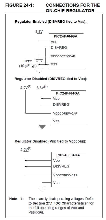
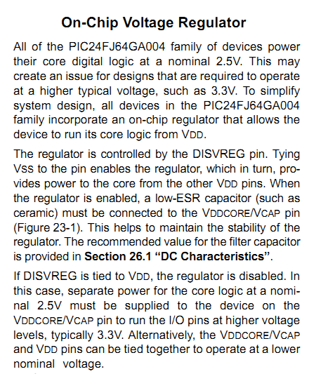
-So do you know to what i should connect the VCAP/VDDCORE pin?
Page 21 of the datasheet says ..................
However, section 27 doesnt tell how to connect this pin when the regulator is disabled.
PIC24FJ64GA004 DATASHEET:
**broken link removed**
I am using PIC24FJ64GA004 and i am not using the on-chip regulator. (i've disabled it)
-So do you know to what i should connect the VCAP/VDDCORE pin?
Page 21 of the datasheet says ..................
When the regulator is disabled, the VCAP/VDDCORE pin
must be tied to a voltage supply at the VDDCORE level.
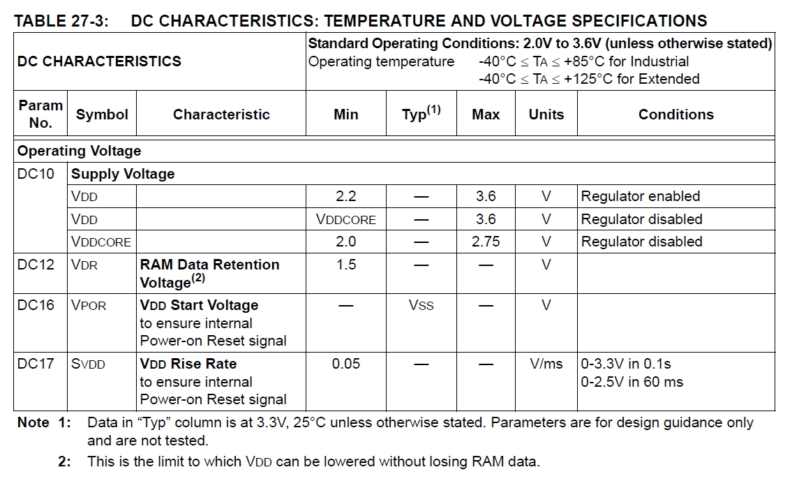
Refer to Section 27.0 “Electrical Characteristics” for
information on VDD and VDDCORE.
However, section 27 doesnt tell how to connect this pin when the regulator is disabled.
PIC24FJ64GA004 DATASHEET:
**broken link removed**