Continue to Site

Welcome to EDAboard.com

Welcome to our site! EDAboard.com is an international Electronics Discussion Forum focused on EDA software, circuits, schematics, books, theory, papers, asic, pld, 8051, DSP, Network, RF, Analog Design, PCB, Service Manuals... and a whole lot more! To participate you need to register. Registration is free. Click here to register now.

Where am i doing wrong???

Status
Not open for further replies.

ex4

Full Member level 2
Joined
Dec 28, 2004
Messages
120
Helped
2
Reputation
4
Reaction score
1
Trophy points
1,298
Location
Jakarta, Indonesia
Activity points
958
tgs5042 application note

hello,
i test this i2v converter, but not working :cry:
the output remain the same. got any suggestion?
 

As long as you have your current source there (I1 1mA) yes it will always be Vo= I1 * R3=3.3V.
 

maybe you need to sweep I1 in DC sweep simulation.
 
The output voltage should be 3.3V. I think the capacitor C1 is too big, at just 1uA it would take long to charge.
Orcad shows the bias calculation results, so if you need to see a graph you can do a DC sweep of source I1 and plot the output voltage vs. I1 or a transient simulation and see the output voltage increasing in time, as the capacitor charges.
It looks like an integrator with resistor for gain limitation at low frequency.
 
You might try using a voltage like 2.5 V on the non-inverting input of the opamp (pin 3).
Could be that the inputs are outside the allowable common-mode input range.
 

run current DC sweep, you should see the variation at DC output voltage
 

done with dc sweep simulation and have seen the output, but when i test it on the real circuit, the expected result is as depicted in the simulation is not the same??? even not near :cry::cry:
i use this circuit to interface TGS5042 CO sensor which its output is current from 0-approximately 1653nA for maximum of 1000ppm CO with increment of 1.653nA/ppm as stated on the marking of the sensor
 

hi,

1, check your amplifier input DC voltage, does your amp work at 0V input?

2, C1 is too large, why do you make it 22uF? please calculte the CAP value based on your bandwidth requirement

Added after 13 minutes:

3, reduce R3 after you increase positive input DC voltage to make sure your output is not too close to supply rail
 

1, check your amplifier input DC voltage, does your amp work at 0V input?
as simulated ,no, it start giving output different at current>=57nA,below that measured 191mV
2, C1 is too large, why do you make it 22uF? please calculte the CAP value based on your bandwidth requirement
it is suggested in the application note, as the sensor stabilized after 1minutes
3, reduce R3 after you increase positive input DC voltage to make sure your output is not too close to supply rail
reducing R3 would increment the minimum measured current,as for the supply rail, i intended to make it as close as possible to supply
 

Please check the input offset voltage of the amp and the CM range of the amplifier.
 

ex4,
The OP-07 is not intended for use with a single supply. Its common mode range does not go to the negative rail. Try using a negative supply instead of gnd. It will work.
Regards,
Kral
 

Dear friend

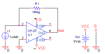
This is a simulation like that, but there isn't any capacitor in it.
DC sweep: I1=0.5µA:4µA , Vout=R1×I1 :arrow: Vout=0.5V:4V.


22_1197935407.gif


Best:D
 
Last edited by a moderator:

I believe, if it is current to voltage converter (Transimepedance amplifier), in the test schematic, the I1 current source is in the wrong direction. By right it should be in the opposite way which means you are injecting the input dc current and not taking out dc current from the opamp. Try it out.
 

Status
Not open for further replies.

Similar threads

Part and Inventory Search

Welcome to EDABoard.com

Sponsor

Back
Top