Terminator3
Advanced Member level 3

- Joined
- Feb 25, 2012
- Messages
- 802
- Helped
- 71
- Reputation
- 142
- Reaction score
- 63
- Trophy points
- 1,308
- Activity points
- 9,027
I know the method of tuning when microstrips are cutted by knife, or soldering a thin copper plate. But there are also some other cool methods using different materials. I whant to know what are the names of that materials, so i can google them and find them.
1) Some kind of dried glue / paint or something.
Where: Usually it put on the microstrip, white or some gray color.
What it does: I guess it locally changes Er, so can be used for phase tuning without cutting
Experience: Removing it degrades circuit performance
Usage: I guess using spectrum analyzer or NA, then put some,remove some glue, put again and so on.
What is the name of this paint? Is there any manufacturers of such things?
2) Some kind of plastic transparent film.
Where: Usually it put above bandpass filters / decoupled microstrip line
What it does: I guess it for less signal losses.
Experience: Removing it degrades output signal level
Usage: Some experience RF designers know how to use
What is the name of this film?
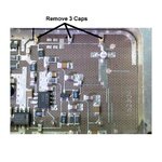
3) Some kind of non-transparent rectangular substance
Where: above decoupled microstrip line, on some stubs, etc.
What it does: I am not sure, some kind of tuning, or maybe resonance?
Experience: removing it does not produced noticeable effect, except it is placed above decoupled microstrip line - degrate output signal level
Usage: Some experience RF designers know how to use
So what is that thing? I guess it is some kind of ceramic or plastic material, but not sure for it futures.
4) Some kind of special RF glue
Where: on DRO-s, etc. glued elements
What it does: not fall off
Experience: i tried two-component glue, some super glue, etc. But never got such good adhesion. Actually original glued DROs is very difficult to unglue without damage. My glue does almost nothing: i can remove puck with my finger.
Usage: glue
I asked for such glue some times ago... But i am not interested in it too much, just need some time to find right glue. But still post it here as PS, maybe some experienced RF designer can suggest me a good glue =)
Are my guesses right? I am reading RF design book, but nothing about such things as paint, transparent film, plastic rectangle or glue. Where i can find info on that?
Thanks!

