Continue to Site

Welcome to EDAboard.com

Welcome to our site! EDAboard.com is an international Electronics Discussion Forum focused on EDA software, circuits, schematics, books, theory, papers, asic, pld, 8051, DSP, Network, RF, Analog Design, PCB, Service Manuals... and a whole lot more! To participate you need to register. Registration is free. Click here to register now.

What kind of circuits output a number of pulses before it goes into a low state?

Status
Not open for further replies.
Re: 20 pulses and circuit goes LOW state, what determines the number of pulses

...What circuit can i put on the output of the 555 timer to counter the pulses and to shut off after 20 pulses?

Calm down...


Firstly, we must apply external components to this 555 device, so that it succeed oscillating.
Find bellow a circuit already referred on another thread at this forum.

7269750206_65703277ce.jpg

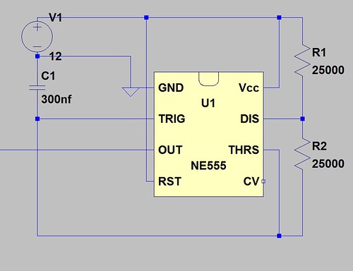
Square Wave by Jason Milich, on Flickr

After you understand this ( oscillator ) circuit, we will gather with another ( monostable ).
But, for now I must certify if remain some doubt up to here.


+++
 

Re: 20 pulses and circuit goes LOW state, what determines the number of pulses

I'm trying not to use a clock, timer, or counter
You do NOT need a clock. Instead you need a clock oscillator to make many pulses, you need a counter to count the pulses but it is usually binary, you need a binary decoder usually made with gates and you need to learn about electronics to identify the circuit.
 

Re: 20 pulses and circuit goes LOW state, what determines the number of pulses

you need a counter to count the pulses

Is there any other IC chip i can use to count the pulses besides a counter? or is there another way of counting pulses?

You do NOT need a clock. Instead you need a clock oscillator to make many pulses

What's the difference? a clock makes many pulses and a oscillator makes many pulses, so what's the difference?

My Manager said that a clock pulse output has to be on the leading edge not the falling edge, I'm not sure what this means, because he said if the clocks output is on the falling edge it can't be synced to anything and the timing is off when a clock is on the falling edge

I have also noticed that if the VCC drifts in voltage it will make the oscillator unstable and it's clock output is drifting in time very slighty
 

Re: 20 pulses and circuit goes LOW state, what determines the number of pulses

Is there any other IC chip i can use to count the pulses besides a counter? or is there another way of counting pulses?
Why? Counter chips are inexpensive and are commonly used for counting.
What's the difference? a clock makes many pulses and a oscillator makes many pulses, so what's the difference?
A clock shows the time, a clock oscillator produces many pulses.

My Manager said that a clock pulse output has to be on the leading edge not the falling edge, I'm not sure what this means, because he said if the clocks output is on the falling edge it can't be synced to anything and the timing is off when a clock is on the falling edge
Some counters like the CD4020, CD4040 and CD4060 are clocked on a negative-going edge and others like the CD4520 are clocked on a positive-going edge. Leading edge or trailing edge are not mentioned on datasheets.
A counter is never sync'd, instead the clock oscillator is sync'd if you want it to be sync'd to another signal.

I have also noticed that if the VCC drifts in voltage it will make the oscillator unstable and it's clock output is drifting in time very slighty
Not true with a 555, or a crystal oscillator or a classic Cmos oscillator. Which oscillator produced your problems?
 

Re: 20 pulses and circuit goes LOW state, what determines the number of pulses

Why? Counter chips are inexpensive and are commonly used for counting.

What circuits don't use a counter chip, but they do counting?

I think at work they use Timing RC networks that go to comparators that trigger and enable a transistor Switch , the timing of the RC network is the counting if that makes sense, because the transistor switches on and off RELATED to the total time of the RC network , when the RC network is fully discharged the voltage is under the threshold voltage of the comparators input

What is this circuit called, i do see them often?

are clocked on a negative-going edge and others like the CD4520 are clocked on a positive-going edge.

This is my problem:

When looking at a clock signal on the O-scope how do u know if the Clock signal is Positive going edge or negative going edge?

How can you tell on the O-scope? do you set the trigger knob to positive or negative ?

Not true with a 555, or a crystal oscillator or a classic Cmos oscillator. Which oscillator produced your problems?

Microcontrollers or Lattice IC chips , they have voltage regulators or zeners on the VCC so the VCC doesn't drift up and down
 

Re: 20 pulses and circuit goes LOW state, what determines the number of pulses

What circuits don't use a counter chip, but they do counting?

I think at work they use Timing RC networks that go to comparators that trigger and enable a transistor Switch , the timing of the RC network is the counting if that makes sense, because the transistor switches on and off RELATED to the total time of the RC network , when the RC network is fully discharged the voltage is under the threshold voltage of the comparators input

What is this circuit called, i do see them often?
You do not make sense.

This is my problem:
When looking at a clock signal on the O-scope how do u know if the Clock signal is Positive going edge or negative going edge?
Two channels 'scope. The clock on one channel and one output of the counter on the other channel. Or look at the datasheet for the counter.

How can you tell on the O-scope? do you set the trigger knob to positive or negative?
It is simple when you learn how to use a 'scope.

Microcontrollers or Lattice IC chips , they have voltage regulators or zeners on the VCC so the VCC doesn't drift up and down
They use a crystal oscillator so that temperature and parts variations do not affect their timing accuracy. VCC does not affect the crystal oscillator.
 

Re: 20 pulses and circuit goes LOW state, what determines the number of pulses

Two channels 'scope. The clock on one channel and one output of the counter on the other channel. Or look at the datasheet for the counter.

Ok I don't get it, you have the clock output on channel#1 and the counters output on channel#2 and you are measuring what? or looking for what? you left part of the story out

Can you tell if the clock signal is positive or negative going edge from the Clocks IC pin output? and how can you tell? cause i can't tell the difference between a clock signal positive or negative going edge
 

Re: 20 pulses and circuit goes LOW state, what determines the number of pulses

Ok I don't get it, you have the clock output on channel#1 and the counters output on channel#2 and you are measuring what? or looking for what? you left part of the story out
The story is obvious to anybody with a brain.
When the output of the counter changes its state (use it to trigger the 'scope) then the clock is going positive or it is going negative.

Can you tell if the clock signal is positive or negative going edge from the Clocks IC pin output? and how can you tell? cause i can't tell the difference between a clock signal positive or negative going edge
I told you to look at the clock when the output of the counter changes its state.
Simple stuff.
 

Re: 20 pulses and circuit goes LOW state, what determines the number of pulses

I told you to look at the clock when the output of the counter changes its state.
Simple stuff.

Not all clock signals have a counter, so how can you tell when putting your O-scope probe on the output pin of the clock? is it positive or negative going edge?

When the output of the counter changes its state (use it to trigger the 'scope) then the clock is going positive or it is going negative.

So you put the counters output pin on the O-scope EXT. TRIGGER ? and sourced Channel#1 clock output to the Counter output pin?
 

Re: 20 pulses and circuit goes LOW state, what determines the number of pulses

Not all clock signals have a counter, so how can you tell when putting your O-scope probe on the output pin of the clock? is it positive or negative going edge?
The positive going and negative going edges of a clock signal are alternating all the time. Then what do you want to know?

So you put the counters output pin on the O-scope EXT. TRIGGER ? and sourced Channel#1 clock output to the Counter output pin?
Again you do not make sense.
Put one output of the counter on channel 1 and put the clock signal on channel 2. Trigger from channel 1.
 

Re: 20 pulses and circuit goes LOW state, what determines the number of pulses

The positive going and negative going edges of a clock signal are alternating all the time. Then what do you want to know?

How do you know if it STARTS or if the clock signal is a positive going or negative going, how do u find out?

Put one output of the counter on channel 1 and put the clock signal on channel 2. Trigger from channel 1.

This will Display the counter's output to the clock signal output, OK and what does this tell u? it's synced? what are u looking at and for on the O-scope display?

You're saying the the counter IC chip inverters the clock signal on the input to the counter IC chip, it converts a positive going edge to a negative going edge? or it takes a negative going edge and converts it to a positive going edge

I guess you can call this inverting? when you convert a positive going edge to a negative going edge? or it takes a negative going edge and converts it to a positive going edge

What's the difference between a positive going edge VS a negative going edge? why do some circuits want a positive going edge and other circuits want a negative going edge?

Is there an advantage for using one or the other?
 

Re: 20 pulses and circuit goes LOW state, what determines the number of pulses

How do you know if it STARTS or if the clock signal is a positive going or negative going, how do u find out?
Why don't you understand that a clock oscillator is running all the time. It never "starts".
Instead you want to know if the clock pin on a counter is activated by a positive-going or a negative-going edge and I told you two ways to find out.

This will Display the counter's output to the clock signal output, OK and what does this tell u? it's synced? what are u looking at and for on the O-scope display?
Why don't you understand anything?
The 'scope is triggered by one output of the counter. The moment it is triggered both traces will be at the left side of the screen. The clock signal is on channel 2 and it goes either positive-going or it goes negative-going at the left side of the screen the moment the counter is activated by the clock edge.

You're saying the the counter IC chip inverters the clock signal on the input to the counter IC chip, it converts a positive going edge to a negative going edge? or it takes a negative going edge and converts it to a positive going edge
I did not say that and again you do not make sense.
Some counter ICs are triggered by a positive-going clock edge and other counter ICs are triggered by a negative-going clock edge.

I guess you can call this inverting? when you convert a positive going edge to a negative going edge? or it takes a negative going edge and converts it to a positive going edge
Nothing is converted and nothing is inverted. I do not know what you are talking about.

What's the difference between a positive going edge VS a negative going edge? why do some circuits want a positive going edge and other circuits want a negative going edge? Is there an advantage for using one or the other?
Who cares? I do not care. That is how they are made. Maybe it has s to do with old fashioned TTL output current is not symmetrical.
Cmos output current is symmetrical so edge direction does not matter.
 

Re: 20 pulses and circuit goes LOW state, what determines the number of pulses

Why don't you understand that a clock oscillator is running all the time. It never "starts".
Instead you want to know if the clock pin on a counter is activated by a positive-going or a negative-going edge and I told you two ways to find out.

So the CLOCK is not "activated" by a positive going or negative going edge? i thought a CLOCK either outputted a positive going edge clock or a negative going edge clock, you had to choose the output of the clock

counter ICs are triggered by a positive-going clock edge and other counter ICs are triggered by a negative-going clock edge.

What internally inside a Counter makes it triggered by a positive or negative going edge? what is inside the counter determining if it's going to be positive or negative going clock edge?

M
aybe it has s to do with old fashioned TTL output current is not symmetrical.
Cmos output current is symmetrical so edge direction does not matter.

What do you mean by the current is symmetrical and not symmetrical?
 

Re: 20 pulses and circuit goes LOW state, what determines the number of pulses

So the CLOCK is not "activated" by a positive going or negative going edge? i thought a CLOCK either outputted a positive going edge clock or a negative going edge clock, you had to choose the output of the clock
A clock oscillator runs or is stopped. Some counters are activated by its positive-going edge of its sq


What internally inside a Counter makes it triggered by a positive or negative going edge? what is inside the counter determining if it's going to be positive or negative going clock edge?

M

What do you mean by the current is symmetrical and not symmetrical?[/QUOTE]

- - - Updated - - -

A clock oscillator runs or is stopped. Some counter ICs are activated by the positive-going edge of its squarewave and other counter ICs are activated by the negative-going edge.

What internally inside a Counter makes it triggered by a positive or negative going edge?
It is simply a squarewave oscillator. It might be stopped sometimes.

what is inside the counter determining if it's going to be positive or negative going clock edge?
Why? Who knows? Who cares?

What do you mean by the current is symmetrical and not symmetrical?
Look at the datasheet of most Cmos gates and counters. They sink and source the same amount of current so the output current is symmetrical. Maybe that is why some use the positive edge and others use the negative edge.
Then look at the datasheet of most 74xx TTL gate and counters to see that they can sink 16mA but can source only 0.4mA so their output current is not symmetrical. Maybe that is why most TTL counters use the negative-going (sinking) edge of clock pulses for activation.
 

Re: 20 pulses and circuit goes LOW state, what determines the number of pulses

Thanks for the info.

Maybe that is why most TTL counters use the negative-going (sinking) edge of clock pulses for activation.

I think this is what my manager was talking to me about, that a clock signal has to be negative going because of this sinking current , because sourcing current takes more power

I guess CMOS IC chips output current is equal with sourcing and sinking so there is no problem of the clock edge direction

They sink and source the same amount of current so the output current is symmetrical. Maybe that is why some use the positive edge and others use the negative edge.

Any Advantage or benefit on using a Positive edge VS a Negative Edge? why use one or the other? for what reason?
 

Re: 20 pulses and circuit goes LOW state, what determines the number of pulses

Any Advantage or benefit on using a Positive edge VS a Negative Edge? why use one or the other? for what reason?
Please do not ask useless questions like this since there is nothing you can do about how this old stuff was made.
 

Status
Not open for further replies.

Part and Inventory Search

Welcome to EDABoard.com

Sponsor

Back
Top