Continue to Site

Welcome to EDAboard.com

Welcome to our site! EDAboard.com is an international Electronics Discussion Forum focused on EDA software, circuits, schematics, books, theory, papers, asic, pld, 8051, DSP, Network, RF, Analog Design, PCB, Service Manuals... and a whole lot more! To participate you need to register. Registration is free. Click here to register now.

What is the value of R1 in below circuit of op-amp ???

Status
Not open for further replies.

jay1691

Member level 2
Member level 2
Joined
Jul 22, 2014
Messages
47
Helped
1
Reputation
2
Reaction score
1
Trophy points
8
Visit site
Activity points
345
Hi,

Please find attached circuit diagram.
As it is in inverting mode, we can apply below formula for Vout calculation.

Vout=-Rf/R1

but here what is the value of R1 ?

Here input is 110v DC. where i have given Gnd of 110V to SGNL_N and positive is given to SGNL_P

Que.JPG
 
Last edited:

can't you just simulate it in pspice or tina-ti? also there is no R1 in the circuit.
 

R35 and R41 forms a by-25 divider (alpha), so that the voltage at the R36 is only 110/25 V.
R30 and R32 forms another divider (beta), but R33 should not be at its good location or useless.
Your "R1" resistor should be R6, so the gain of this inverter is "-1" (considering the output drives an impedance >20k).

Considering you will remove R33, Vout= - (alpha*SGN_P)-(beta*SGN_N)
 

hii zoulzubazz,

I have simulate it.
Below is test result.
Input= 110V DC
Vout= -2.97V.
But i am wondering how it comes ??
Because as we go from theory, here GND (GND OF 110V DC) is given to non inverting terminal of op-amp.Here i neglect voltage divider forms by R30 and R32 because input is GND.
and here because of R35 and R41 voltage divider voltage at that node should be 4.4V.
and if i take r36=r1 and r39=rf then
Av = -rf/r1
Av= - (2/2)
Av=-1
so Vout=Av*vin
Vout= -1 (4.4) (here i take vin=4.4 because R35 and R41 voltage divider )
Vout= -4.4
So according theory it should be -4.4 but i got -2.97V.

please solve it
 

DO NOT remove R33. It is part of the differential amplifier circuit. Simply look at Differential Amplifier in Google and it will show you that your R31 and R36 are R1 on some schematics of a differential amplifier like this one attached.
Your circuit is wrong because each voltage divider has a different output because one is loaded with R31 plus R33= 4k but the other is loaded with only R36 which is 2k.
 

Attachments

  • differential amplifier.png
    differential amplifier.png
    7.6 KB · Views: 179
Hi Audioguru,

Thanks for reply.
It is bit clear from your reference circuit but here i can said that in my circuit same divider is used.
here R30,R32 is used for (+) and R35,R41 is used for (-) terminal as voltage divider.Both divider has same resister values.
Now remain circuit is exactly match with your reference circuit.

So here if i will apply equation of Vout= (V2-V1)R3/R1

So as you said R36,R31 is R1=2K and R3=R39=2K
Vout=(V2-V1)(2/2)
Vout=(V2-V1)
Here V2= Gnd of 110V so it will 0

Vout= -V1
Am I right ??

And here V1 node is After divider of R30 and R32.
So if i have applied 110V DC in input then because of R30 and R32 it will 4.4V at node V1.

So output should be Vout= -V1 = -4.4V.

Is it correct ???
 

The load on the R30 and R32 voltage divider is 4k ohms but the load on the R35 and R41 voltage divider is only 2k ohms so they do not match. Then the common mode rejection is poor and the gain is not what you think.
Change R35 to 12k and change R41 to two 1k resistors in parallel. Then the differential amplifier will be balanced.
 
Hi Audioguru,

its great.
i have put this two values in simulation and output rail goes to -3.54 (before it was -2.97). so it is increase.
But still it should be -4.4.
And can you please tell me how you selected value 12K and 500R(two parellel 1k) ??
Is there any equation or method to select this value ?
 

Why bother with the input dividers, they just make the maths hairy, if instead you went with a differential amp with a gain of say 0.04 or so then you would use fewer components and potentially have less power dissipated in the dividers (use 100K input resistors or so, with say 3.9K resistors in the feedback and non inverting gain setting position.

Another option would be to raise the values of all the 2K resistors in your circuit to be very much greater (at least a few tens of K), which will make the effect of the load presented by the difference amplifier to the input dividers small and thus reduce the impact on the ratios.

Do remember to make sure sane things happen if the 110V battery is connected before the opamp is powered.

Regards, Dan.
 
I agree that the post #1 differential amplifier cicuit may be simplified to a four-resistor differential amplifier, as suggested. Of course this also eases calculation.

The original circuit is however a valid differential amplifier circuit, there's nothing missing or wrongly dimensioned. It has infinite CMRR with ideal resistor values and ideal OP, similar to the four-resistor circuit. Its differential gain can be determined by applying basic linear network calculation methods.

- - - Updated - - -

2.97 V (1/37 of input voltage) is the exact circuit gain with ideal OP.

Differential and common mode gain have to be determined. Shown that the common mode gain is zero, you can assum SGNL_N = 0 and reduce analysis to the network connected to inverting input.

SGNL_P gain is -1/(R35*(R36+R41)/(R36*R41) + 1)*R39/R36 = -1/37
 
Dear FvM,

Your ans is really helpful. i need this type of equation which let me know how the output comes.

As i have applied that equation for 12K and 500R value which is given by Audioguru and that equation is also worked for that.i got exact -3.54 v answer.


Can you please tell me how that equation come or give me suggestion or steps for making that equation ??

Thank you a lot for your answers.
 

A handy formula for determining the equivalent input or feedback resistance of a "Tee" network is:
.
Req = R31+R34 + (R31 X R34)/R36
.
The formula only works if both the input and output of the Tee are at ground or virtual ground.
 
Hii Kral,

As per your equation " Req = R31+R34 + (R31 X R34)/R36 " But here there is nothing like R34 resistor in my circuit so can you please re update with new designator (Reference) resistor number.
 

Sorry jay1691. I must have been asleep when I replied.
.
The correct formula is Req = R35 + R36 + (R35 X R36)/R41.
Regards,
Kral
 
Hi Kral,

No need to say sorry and thanks a lot for your answer.

Can you provide me any link or reference document for this handy formula ?
So i can understand how that formula comes.
 

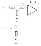
The equivalent input resistor R1 is Equal to the input voltage Vi Divided by the current into the summing junction (Iin) as shown in Fig 1. Since the feedback resistor R39 holds the inverting input at virtual ground, we can replace the "Tee" network with the equivalent circuit of Fig 2 for the purpose of calculating the Voltage Va and the current Iin.
Rp = R41 X R36 / (R41 +R36)
Va = Vin X Rp/(Rp + R35)
Substituting for Rp:
Va = Vin X (R41 X R36 /(R41 + R36) /( R41 X R36 /(R41 + R36) + R35))
Multiplying Numerator and Denominator by (R41 + R36):
Va = Vin X (R41 X R36 / (R41 X R36 + R35 X (R41 + R36)))
Va = Vin X R41 X R36 /( R41 X R36 + R35 X R41 + R35 X R36)
Iin = Va/R36
Substituting for Va:
Iin = Vin X R41/(R41 X R36 + R35 X R41 + R35 X R36)
Req = Vin / Iin
Req = 1 / (R41 / (R41 X R36+ R35 X R41 + R35 X R36))
Req =( R41 X R36 + R41 X R35 + R35 X R36) / R41
Req = R36 + R35 + R36 X R35 / R41T Network EDA Reply Drawing Cropped.jpg

- - - Updated - - -

The equivalent input resistor R1 is Equal to the input voltage Vi Divided by the current into the summing junction (Iin) as shown in Fig 1. Since the feedback resistor R39 holds the inverting input at virtual ground, we can replace the "Tee" network with the equivalent circuit of Fig 2 for the purpose of calculating the Voltage Va and the current Iin.
Rp = R41 X R36 / (R41 +R36)
Va = Vin X Rp/(Rp + R35)
Substituting for Rp:
Va = Vin X (R41 X R36 /(R41 + R36) /( R41 X R36 /(R41 + R36) + R35))
Multiplying Numerator and Denominator by (R41 + R36):
Va = Vin X (R41 X R36 / (R41 X R36 + R35 X (R41 + R36)))
Va = Vin X R41 X R36 /( R41 X R36 + R35 X R41 + R35 X R36)
Iin = Va/R36
Substituting for Va:
Iin = Vin X R41/(R41 X R36 + R35 X R41 + R35 X R36)
Req = Vin / Iin
Req = 1 / (R41 / (R41 X R36+ R35 X R41 + R35 X R36))
Req =( R41 X R36 + R41 X R35 + R35 X R36) / R41
Req = R36 + R35 + R36 X R35 / R41T Network EDA Reply Drawing Cropped.jpg
 
Replacing R35, R36 and R41 with a single series resistor whose value is
( R41 X R36 + R41 X R35 + R35 X R36) / R41 will give the same gain for a signal applied at SGNL_P, provided that the impedance of the signal source is zero. If the impedance of the source driving SGNL_P is not zero, then the gain in the two cases will not be the same, because the input resistance of the tee network is not equal to ( R41 X R36 + R41 X R35 + R35 X R36) / R41.

Kral alluded to this fact when he said "The formula only works if both the input and output of the Tee are at ground or virtual ground.", so beware.
 
Status
Not open for further replies.

Similar threads

Part and Inventory Search

Welcome to EDABoard.com

Sponsor

Back
Top