xpress_embedo
Advanced Member level 4

I am using PIC18F4550, with the following Schematic
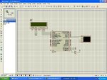
My Code is as follow:
Lcd 4 Bit Library
But nothing comes on the display.
I am also attaching the full MPLAB X project, written in version 3.10 and XC8 version 1.35

My Code is as follow:
Code C - [expand] 1 2 3 4 5 6 7 8 9 10 11 12 13 14 15 16 17 18 19 20 21 22 23 24 25 26 27 28 29 30 31 32 33 34 35 36 37 38 39 40 41 42 43 44 45 46 47 48 49 50 51 52 53 54 55 56 57 58 59 60 61 62 63 64 65 66 67 68 69 70 71 72 73 74 75 76 77 78 79 80 #include <xc.h> #include "UART.h" #include "LCD.h" // CONFIG1L #pragma config PLLDIV = 5 // PLL Prescaler Selection bits (Divide by 5 (20 MHz oscillator input)) #pragma config CPUDIV = OSC1_PLL2// System Clock Postscaler Selection bits ([Primary Oscillator Src: /1][96 MHz PLL Src: /2]) #pragma config USBDIV = 2 // USB Clock Selection bit (used in Full-Speed USB mode only; UCFG:FSEN = 1) (USB clock source comes from the 96 MHz PLL divided by 2) // CONFIG1H #pragma config FOSC = HSPLL_HS // Oscillator Selection bits (HS oscillator, PLL enabled (HSPLL)) #pragma config FCMEN = OFF // Fail-Safe Clock Monitor Enable bit (Fail-Safe Clock Monitor disabled) #pragma config IESO = OFF // Internal/External Oscillator Switchover bit (Oscillator Switchover mode disabled) // CONFIG2L #pragma config PWRT = OFF // Power-up Timer Enable bit (PWRT disabled) #pragma config BOR = ON // Brown-out Reset Enable bits (Brown-out Reset enabled in hardware only (SBOREN is disabled)) #pragma config BORV = 3 // Brown-out Reset Voltage bits (Minimum setting) #pragma config VREGEN = ON // USB Voltage Regulator Enable bit (USB voltage regulator enabled) // CONFIG2H #pragma config WDT = OFF // Watchdog Timer Enable bit (WDT disabled (control is placed on the SWDTEN bit)) #pragma config WDTPS = 32768 // Watchdog Timer Postscale Select bits (1:32768) // CONFIG3H #pragma config CCP2MX = ON // CCP2 MUX bit (CCP2 input/output is multiplexed with RC1) #pragma config PBADEN = OFF // PORTB A/D Enable bit (PORTB<4:0> pins are configured as digital I/O on Reset) #pragma config LPT1OSC = OFF // Low-Power Timer 1 Oscillator Enable bit (Timer1 configured for higher power operation) #pragma config MCLRE = ON // MCLR Pin Enable bit (MCLR pin enabled; RE3 input pin disabled) // CONFIG4L #pragma config STVREN = ON // Stack Full/Underflow Reset Enable bit (Stack full/underflow will cause Reset) #pragma config LVP = OFF // Single-Supply ICSP Enable bit (Single-Supply ICSP disabled) #pragma config ICPRT = OFF // Dedicated In-Circuit Debug/Programming Port (ICPORT) Enable bit (ICPORT disabled) #pragma config XINST = OFF // Extended Instruction Set Enable bit (Instruction set extension and Indexed Addressing mode disabled (Legacy mode)) // CONFIG5L #pragma config CP0 = OFF // Code Protection bit (Block 0 (000800-001FFFh) is not code-protected) #pragma config CP1 = OFF // Code Protection bit (Block 1 (002000-003FFFh) is not code-protected) #pragma config CP2 = OFF // Code Protection bit (Block 2 (004000-005FFFh) is not code-protected) #pragma config CP3 = OFF // Code Protection bit (Block 3 (006000-007FFFh) is not code-protected) // CONFIG5H #pragma config CPB = OFF // Boot Block Code Protection bit (Boot block (000000-0007FFh) is not code-protected) #pragma config CPD = OFF // Data EEPROM Code Protection bit (Data EEPROM is not code-protected) // CONFIG6L #pragma config WRT0 = OFF // Write Protection bit (Block 0 (000800-001FFFh) is not write-protected) #pragma config WRT1 = OFF // Write Protection bit (Block 1 (002000-003FFFh) is not write-protected) #pragma config WRT2 = OFF // Write Protection bit (Block 2 (004000-005FFFh) is not write-protected) #pragma config WRT3 = OFF // Write Protection bit (Block 3 (006000-007FFFh) is not write-protected) // CONFIG6H #pragma config WRTC = OFF // Configuration Register Write Protection bit (Configuration registers (300000-3000FFh) are not write-protected) #pragma config WRTB = OFF // Boot Block Write Protection bit (Boot block (000000-0007FFh) is not write-protected) #pragma config WRTD = OFF // Data EEPROM Write Protection bit (Data EEPROM is not write-protected) // CONFIG7L #pragma config EBTR0 = OFF // Table Read Protection bit (Block 0 (000800-001FFFh) is not protected from table reads executed in other blocks) #pragma config EBTR1 = OFF // Table Read Protection bit (Block 1 (002000-003FFFh) is not protected from table reads executed in other blocks) #pragma config EBTR2 = OFF // Table Read Protection bit (Block 2 (004000-005FFFh) is not protected from table reads executed in other blocks) #pragma config EBTR3 = OFF // Table Read Protection bit (Block 3 (006000-007FFFh) is not protected from table reads executed in other blocks) // CONFIG7H #pragma config EBTRB = OFF // Boot Block Table Read Protection bit (Boot block (000000-0007FFh) is not protected from table reads executed in other blocks) void main() { unsigned char msg[] = "Keyboard Test Program!\r\n"; unsigned char receive = 0; ADCON1 = 0x0F; Lcd4_Init(); UART_Init(); UART_Write_Text(msg); Lcd4_Write('A'); { receive = UART_Read(); UART_Write(receive); } }
Lcd 4 Bit Library
Code C - [expand] 1 2 3 4 5 6 7 8 9 10 11 12 13 14 15 16 17 18 19 20 21 22 23 24 25 26 27 28 29 30 31 32 33 34 35 36 37 38 39 40 41 42 43 44 45 46 47 48 49 50 51 52 53 54 55 56 57 58 59 60 61 62 63 64 65 66 67 68 69 70 71 72 73 74 75 76 77 78 79 #include "LCD.h" void Lcd4_Cmd(unsigned char value) { LCD_RS = 0; LCD_DATA = (value>>4) & 0x0F; LCD_EN = 1; __delay_ms(10); LCD_EN = 0; LCD_DATA = (value & 0x0F); LCD_EN = 1; __delay_ms(10); LCD_EN = 0; __delay_ms(1); } void Lcd4_Write(unsigned char value) { LCD_RS = 1; LCD_DATA = (value>>4) & 0x0F; LCD_EN = 1; __delay_ms(10); LCD_EN = 0; LCD_DATA = (value & 0x0F); LCD_EN = 1; __delay_ms(10); LCD_EN = 0; __delay_ms(1); } void Lcd4_Write_Text(unsigned char msg[]) { while(*msg) { Lcd4_Write(*msg); msg++; } } void Lcd4_Init(void) { __delay_ms(10); __delay_ms(10); TRISA = 0x00; TRISEbits.TRISE0 = 0; TRISEbits.TRISE1 = 0; TRISEbits.TRISE2 = 0; LCD_RS = 0; //Command Register LCD_RW = 0; LCD_EN = 0; LCD_DATA = 0x03; LCD_EN = 1; __delay_ms(10); LCD_EN = 0; __delay_ms(10); LCD_EN = 1; __delay_ms(10); LCD_EN = 0; __delay_ms(10); LCD_EN = 1; __delay_ms(10); LCD_EN = 0; __delay_ms(10); LCD_DATA = 0x02; // Four bit mode LCD_EN = 1; __delay_ms(10); LCD_EN = 0; __delay_ms(10); Lcd4_Cmd(0x28); Lcd4_Cmd(0x0C); Lcd4_Cmd(0x01); Lcd4_Cmd(0x06); }
But nothing comes on the display.
I am also attaching the full MPLAB X project, written in version 3.10 and XC8 version 1.35