Continue to Site

Welcome to EDAboard.com

Welcome to our site! EDAboard.com is an international Electronics Discussion Forum focused on EDA software, circuits, schematics, books, theory, papers, asic, pld, 8051, DSP, Network, RF, Analog Design, PCB, Service Manuals... and a whole lot more! To participate you need to register. Registration is free. Click here to register now.

What do the terms fan-out and fan-in mean?

Status
Not open for further replies.

weng

Member level 1
Joined
Jan 13, 2006
Messages
32
Helped
0
Reputation
0
Reaction score
0
Trophy points
1,286
Activity points
1,576
What does the term fan-out (and fan-in) means? How to calculate it (them)?
 

fanout calculation digital

fanout means the number of connected!!
 

fanout equation ttl

The number of drive gates!
 

how to calculate fan out

fan-out

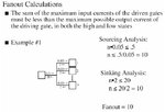
Fan-out is a term that defines the maximum number of digital inputs that the output of a single logic gate can feed. Most transistor-transistor logic (TTL) gates can feed up to 10 other digital gates or devices. Thus, a typical TTL gate has a fan-out of 10.
In some digital systems, it is necessary for a single TTL logic gate to drive more than 10 other gates or devices. When this is the case, a device called a buffer can be used between the TTL gate and the multiple devices it must drive. A buffer of this type has a fan-out of 25 to 30. A logical inverter (also called a NOT gate) can serve this function in most digital circuits.

Regards,
IanP
 

calculate fan out

Most transistor-transistor logic (TTL) gates can feed up to 10 other digital gates or devices. Thus, a typical TTL gate has a fan-out of 10.


But how to derive this statement? How to calculate the fan-out?
 

logic deviced and fan out what does it mean

Fanin of a cell is all the other cells that drive the cell.
Fanout of a cell is all the other cells driven by the cell.
Take a look at following link to see how GOF trace the fanin/out on a schematic.

https://www.nandigits.com/trace_fanin_fanout.htm

Nandy
www.nandigits.com
Netlist Debug/ECO in GUI mode.
 

cmos fan in fan out questions

Below you can find example on how to calculate fan-out ..
All currents (in mA) are given for standard TTL gates, for different gates these currents can be found in gates' data sheets ..

Regards,
IanP
 

Attachments

  • fanout_calculations_200.jpg
    fanout_calculations_200.jpg
    39 KB · Views: 528

how to calculate fan out of a digital ttl logic

Hi all,

Thanks for your explaination.

It looks like current is the parameter that determines fan-out. How about delay? Initially, I thought that delay time is the parameter that cost fan-out.

Please advise.
 

calculating buffer fan out from drive strength

IanP,

I have a doubt.As per the example given,you said sourcing current .5 is the max. OK I accept it.Because if the device loaded than .5 each component will get less current so that they might not turn ON.

But why the sinking current has to be less than 20. Can you throw some light on to it.

GD
 

how to calculate fan-in digital

There is no such a requirement that the sinking current in this example must be <20mA ..
It is (n * 2mA) which has to be smaller or equal to 20mA .. and from this equation one can estimate the number 'n' ..
That's all ..

Regards,
IanP
 

fanout calculation

Hi,

Question again...

How to calculate the input current and output current? Is it governed by the equa
I(sat) = k/2 • W/L • (Vgs - Vt)² and I(lin) = k/2 • W/L • [2(Vgs-Vt)Vds-Vds²]?

As far as I know, CMOS inverter does not consume any current in steady-state. So does it mean that the current you mention above is the current yield during switching? Or it is avg current?
 

fan out calculation for ttl

by increasing output drive strength, we can increase the fan-out.
 

what is fan-in and fan-out for ttl

gud question weng...actually the explaination above explains drive strength concept for a BJT where inout current i.e base current is essential for the switch to work....now in a MOS this scenario is totally changed....here it is important to charge and discharge load capacitances rather than supply base currents hence the concept of delay also appears as pointed by someone earlier.... now what we actually do is to calibrate a standard gate load an then as per fanout requirement with those loads we apply a input to given design with varible slew's...u cna find this data in delay matrix of any standard cell library...this is how cells are characterised...
hope im of some help...
 

    weng

    Points: 2
    Helpful Answer Positive Rating
    V

    Points: 2
    Helpful Answer Positive Rating
calculate fanout

Hi eda_freak,

Do you mean that fanout requirement of CMOS gate actually depends on the delay?
 

fan out of digital ic calculation

fan out is the maximum number of the gates of the same family that a gate can drive.
 

fanout calculation for ttl logic gates

the number of fanout is that the caculate number the output drive of a gate is connect to the other cell input load. The input load is define in the library.
 

fanout calculation ttl logic gates

fanout is the maximum number of gates of the same family that a gate can drive
 

Status
Not open for further replies.

Part and Inventory Search

Welcome to EDABoard.com

Sponsor

Back
Top