Continue to Site

Welcome to EDAboard.com

Welcome to our site! EDAboard.com is an international Electronics Discussion Forum focused on EDA software, circuits, schematics, books, theory, papers, asic, pld, 8051, DSP, Network, RF, Analog Design, PCB, Service Manuals... and a whole lot more! To participate you need to register. Registration is free. Click here to register now.

[SOLVED] weird counter problem

Status
Not open for further replies.

khansaab21

Advanced Member level 4
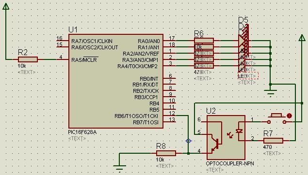
Joined
Apr 12, 2008
Messages
108
Helped
4
Reputation
8
Reaction score
2
Trophy points
1,298
Activity points
2,214
Device: PIC16F628A
Compiler: MikroC

Program Description: This is a simple test program in which timer1 is configured for counter operation. Counter has to be read every 10 sec and the maximum number of counts are 233 in that interval. Hence, only TMR1L is more than enough to be read.

Problem: Every external pulse on the counter pin increases '3' in the register rather than increasing '1'. Can anybody please hepl me with that.
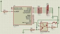
Schematic:


Code:

void main() {
CMCON |= 7; // Disable Comparators
TRISA = 0; // Setting in output mode
TRISB.B6 = 1; // Making it input for counter inputs

T1CON = 6; // Initializing Timer1 for asynchronous counter operation
TMR1H = 0; // Clearing upper byte

for (;;)
{
// Resetting variables and registers
TMR1L = 0;

T1CON.B0 = 1; // Enable Timer 1
Delay_ms(5000); // Wait for 10 sec
T1CON.B0 = 0; // Disable Timer 1
PORTA = TMR1L;
}
}

Note:
Input has to be through opto coupler.
 

Every external pulse on the counter pin increases '3' in the register rather than increasing '1'
The most likely explanation is a bouncing pushbutton. You can either use external pulse shaping (RC filter and schmitt
trigger gate) or a software counter with respective debounce delay instead of hardware timer.
 

1. I dont totally understand what do you mean by 'requirements', but following is a brief description of this project.
A circular plate with a single slot is attached to the shaft of the motor. A photo coupler is placed such that the beam gets cut once on one complete rotation of the shaft. Those cuts are translated into HI/LO levels or counts counted by the controller. Counts are accumulated for 10 sec, processed (like multiplied by 6, converted to ascii, etc) and resultant rpm is displayed on LCD.
Every thing is working as it should except this counter thing. On every HI, it should increase 1 in the timer register, but instead it is increasing in multiples of 3. And thats weird and definitely not required.

2. Input is not through button (its just there for simulation purposes). Real input is through is photo coupler.
 

Hi,

This is definitely not 10 sec but 5 sec :

Delay_ms(5000); // Wait for 10 sec

The right syntax for mikroC is this one :

void main() {
CMCON |= 7; // Disable Comparators
TRISA = 0; // Setting in output mode
TRISB.F6 = 1; // Making it input for counter inputs

T1CON = 6; // Initializing Timer1 for asynchronous counter operation
TMR1H = 0; // Clearing upper byte

for (;;)
{
// Resetting variables and registers
TMR1L = 0;

T1CON.F0 = 1; // Enable Timer 1
Delay_ms(5000); // Wait for 10 sec
T1CON.F0 = 0; // Disable Timer 1
PORTA = TMR1L;
}
}
 

@Hugo, my bad, as this is just a test program, therefore I made it 5 sec. Originally it was 10 sec.

Any ways, the problem has been solved. I was simulating in Proteus and it was showing such results. How ever, my group member down loaded the same program in the chip and surprisingly, the results were correct.
The main problem has been solved, but I wonder, why proteus was showing such erroneous results.
 

Status
Not open for further replies.

Similar threads

Part and Inventory Search

Welcome to EDABoard.com

Sponsor

Back
Top