jianke
Member level 3

- Joined
- Oct 22, 2010
- Messages
- 55
- Helped
- 0
- Reputation
- 0
- Reaction score
- 0
- Trophy points
- 1,286
- Activity points
- 1,764
Hi everyone,
I am not sure how to choose the size of waveport in Driven Terminal. Can anyone give me some suggestion?
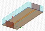
The dimensions of my structure (see the attached picture or HFSS file):
Height of substrate, h=0.762mm;
Width of microstrip line, w=1.98mm;
Operation frequency, f=14.25GHz;
Wavelength=21.053mm; Wavelength/2=10.526mm, Wavelength/4=5.263
According to the HFSS manual (w>h),
Height of waveport = 6h~10h
Width of waveport = 10w=19.8mm
However, the height and width of waveport cannot exceed the Wavelength/2 (10.526mm)!!!
Thus, I choose 6.762mm as waveport height, and 10mm as waveport width.
The operation frequency is f=14.25GHz, and I want to sweep from 1GHz to 25GHz.
Whether the waveport size I choosed is correct, espically the width?
 View attachment Shield.rar
I am not sure how to choose the size of waveport in Driven Terminal. Can anyone give me some suggestion?
The dimensions of my structure (see the attached picture or HFSS file):
Height of substrate, h=0.762mm;
Width of microstrip line, w=1.98mm;
Operation frequency, f=14.25GHz;
Wavelength=21.053mm; Wavelength/2=10.526mm, Wavelength/4=5.263
According to the HFSS manual (w>h),
Height of waveport = 6h~10h
Width of waveport = 10w=19.8mm
However, the height and width of waveport cannot exceed the Wavelength/2 (10.526mm)!!!
Thus, I choose 6.762mm as waveport height, and 10mm as waveport width.
The operation frequency is f=14.25GHz, and I want to sweep from 1GHz to 25GHz.
Whether the waveport size I choosed is correct, espically the width?
 View attachment Shield.rar
