Continue to Site

Welcome to EDAboard.com

Welcome to our site! EDAboard.com is an international Electronics Discussion Forum focused on EDA software, circuits, schematics, books, theory, papers, asic, pld, 8051, DSP, Network, RF, Analog Design, PCB, Service Manuals... and a whole lot more! To participate you need to register. Registration is free. Click here to register now.

Water Level Measurement and tap control

Status
Not open for further replies.

anantj18

Newbie level 3
Joined
Aug 6, 2011
Messages
4
Helped
0
Reputation
0
Reaction score
0
Trophy points
1,281
Location
Chennai,India
Activity points
1,324
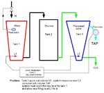
Hi i am trying to design a water tank system. Here the user pours water into one tank, the water after processing through the second tank, gets stored in the third tank. Now the challenge is that the amount of extra water that is poured into the first tank should be the amount of water coming out from the third tank. Can anyone give any suggestions ?
 

Do I understand your problem correctly

Pour & Fill 01.jpg


We must to know the shape of the tanks
ie what is the relationship between changes in volume and height for both tanks

When we know these functions, we can calculate the relationship between levels.

KAK
 

Hey KAK,

You've exactly understood my problem. The point regarding the height you have raised is the exact thing that i want to avoid. The thing is that when a user pours water, the volume(height) in the input increases, and when he takes out water from the output the volume in the output(height) decreases, now since the water is being processed in the second tank hence, it will take some time for the system to reach it's original (steady) state. So at any time the height (pressure) in both the tanks is different, changing the rate of flow of volume. So if, say I include a float switch in the input tank and allow connect the output tank tap to the flow meter, then the water actually coming out from the output tank will be different from the water poured into the input.

I hope i'm able to convey the problem clearly.

---------- Post added at 03:40 ---------- Previous post was at 03:39 ----------

Hey KAK,

You've exactly understood my problem. The point regarding the height you have raised is the exact thing that i want to avoid. The thing is that when a user pours water, the volume(height) in the input increases, and when he takes out water from the output the volume in the output(height) decreases, now since the water is being processed in the second tank hence, it will take some time for the system to reach it's original (steady) state. So at any time the height (pressure) in both the tanks is different, changing the rate of flow of volume. So if, say I include a float switch in the input tank and allow connect the output tank tap to the flow meter, then the water actually coming out from the output tank will be different from the water poured into the input.

I hope i'm able to convey the problem clearly.
 

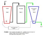
I made changes in picture

Pour & Fill 02.jpg


We must to know the shape of the tanks
ie what is the relationship between changes in volume and height for both tanks

When we know these functions, we can calculate the relationship between levels
and correct this with calculated change of level by using measured tap volume.

But when we know the tap volume , we can calculate how much it means in level tank 3
and fill tank 3 to that level with pure water , after processed material from tank 2 was moved to tank 3
(supposition : tap is mostly water )

( or ??? )


KAK
 
Last edited:

Hey Kak,

I am planing to do soething similar to the first sketch you have sent, cause clearly float meter is not going to work, again the tank is cylindrical with a diameter of .6604m.(26 inches) and a volume capacity of .3 meter cube (300 L)
 

So tank 1 is vertical sylinder diameter 0.66 cm
ie. 1cm in water level is 3.421 liter

how about shape of tank 3.

( for measuring devices : are tanks open or closed )
or have you allready some level measuring equipments installed

How is tank 3 poured out ( randomly , small flow all the time , all at once )
What is main reason for tap ( overflow , evaporation )

KAK
 

Hey Kak,
The tank 1 is cylinder with diameter 0.66m and not 0.66cm.
The water measurement device is what i'm not sure about.
The area of tank comes out to be .0342 meter square. Therefore if i add 1 L(.001 meter cube) of water i'll get a height raise of only 2.92mm, so i'll need a level measurement sensor which can detect even this small change in height and give ma some voltage or current output.
The output tank can be assumed to be of similar dimensions.

The main reason for the tap in the third tank is to draw water out. Again the water drawn out should be equal to the
water poured into the input, so the tap needs to be an electronic tap which works with regard to feedback given by the
level measurement sensor in tank 1
 

What we know is

tank 1 and 3 are cylinders diam. 66 cm
ie. 10 mm in level is 3.421 liters in volume
or 1 liter in volume is 2.923 mm in level

Measured change in level is 1 m
if resolution in measurement is 1 liter , it means measured accuracy 0.29 % ( 1m )
that is hard to achieve without expensive devices

If we use electronic devices , first becomes the level sensor ie.
device that transform level to voltage ( or current )

Measuring principles:
-ultrasonic
-capacitive
-laser
-float

Discussions of measuring fluid level

....look my advice in 22-04-11 15:23 i think it is maybe useful in this problem.....
https://www.edaboard.com/threads/210078/

https://www.edaboard.com/threads/73543/

https://www.edaboard.com/threads/212696/

https://www.edaboard.com/threads/106756/

https://www.edaboard.com/threads/131487/

https://www.edaboard.com/threads/154202/

and many many more.....................

KAK
 

Status
Not open for further replies.

Part and Inventory Search

Welcome to EDABoard.com

Sponsor

Back
Top