Continue to Site

Welcome to EDAboard.com

Welcome to our site! EDAboard.com is an international Electronics Discussion Forum focused on EDA software, circuits, schematics, books, theory, papers, asic, pld, 8051, DSP, Network, RF, Analog Design, PCB, Service Manuals... and a whole lot more! To participate you need to register. Registration is free. Click here to register now.

Water leak detector circuit using water conductivity principle

Status
Not open for further replies.

redreobingarden

Newbie level 3
Joined
May 24, 2012
Messages
3
Helped
0
Reputation
0
Reaction score
0
Trophy points
1,281
Activity points
1,333
Hello! I am an idiot when it comes to analog circuit design.

So, I have a sealed electronic enclosure that will be going underwater. I am designing a circuit board to do some stuff and communicate with a topside computer. I figured, well if I'm designing the circuit board, why not add a simple "leak sensor" based on the conductivity between two bare traces on the board.

This led to me trying to design a simple leak detector that will send a logic signal from 0 to 5 volts (the actual logic level 0 needs to be a voltage less than 1.0 and the logic high is a voltage higher 2.4v)

Essentially it needs to be something like this:
LeakSensor.jpg

So I did some resistance measurement of water and I'm getting something around 100K - 300K ohms resistance value for two probes that are close to each other in water.

I figured I need to use a transistor and have the base resistor be the "leak sensor traces". I started playing around with a simple NPN transistor and did some calculations on what other resistor values I should use but I really have no idea what I'm doing.
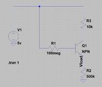
Schematic.JPG

Anyone have any pointers on how I should design this circuit?

Thanks!
-Paul
 

I once made a similar water detector. I found I had to use a darlington arrangement (two transistors arranged so their gain is multiplied).

I wanted maximum sensitivity, so I put a wire where you have R2. I put a buzzer where you have R3.

The sensor wires were close together, not touching. I did not install anything where you have R1.

My detector worked fine when I first made it. The buzzer sounded when water spanned both sensor wires.

I checked it two days later. I found it had completely drained the 9V battery, yet there was no alarm, nor did water get on the sensor wires.
 

To make some sense, assuming that R1 acts as the probe sensor, you should replace it by a smaller value in the range of some houndred kohms, as well tie Q1 emmiter to GND. The voltage measured at Q1 collector could be understood like the water detection. Obviously, Q1 should have a high gain, prefereably the darlington type.

In my oppinion, you could think about use another approach, not with a BJN trnsistor, but with a MOSFET. Anyway, still on the current circuit, you must be aware that the water conductance varies significantly acording to its temperature and ions dissolved there.
 

-leakage sensors are unreliable with wide variation in results with corrosion , dust, moisture.
- capacitance method is preferred.

It is easy to setup a Schmitt trigger with a fixed threshold and a bias resistor , but the leakage with humidity in dust may give false readings over time.

BTW
Water does not conduct DC
only ions or contamination or salts or acids or bases conduct in the insulator medium.
 

A similar subject was discussed here, and interesting insights arose.
 

Thank you for your replies!

-leakage sensors are unreliable with wide variation in results with corrosion , dust, moisture.
- capacitance method is preferred.

It is easy to setup a Schmitt trigger with a fixed threshold and a bias resistor , but the leakage with humidity in dust may give false readings over time.

BTW
Water does not conduct DC
only ions or contamination or salts or acids or bases conduct in the insulator medium.

Brad I think a capacitance sensor is overkill for my needs. This sensor should never see liquid in its life and is only expected to go off if disaster happens, so corrosion is not a factor. It will not see cyclic duty in wet environments like.. say for example.. a soil moisture sensor.

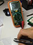
After doing some more work on it I've narrowed down my design requirements to still having the conductive based sensor that will go 0v to 5v when the resistance between two bare traces goes from infinity (meaning the traces are in air) to <1M. I did some simple resistance testing using two wires with a bit of lake water across them.
IMG_5897.JPG

I switched up my circuit to the following:
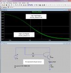
water_sensor_2.jpg

RI represents the PCB trace "sensor". Shown in the graph is a simulation of the "sensor_output" trace relative to resistance values seen at R1. Ideally, this would have a step response, going from 5v to 0v at that perfect resistance threshold where there is either air or a water drop on in between the traces.

So I changed up the transistor to a darlington (TIP142, only one i could find in LTspice) and played around with R4. Again, i have no idea what i'm doing, but it seems that by playing with R4 I can tweak sensor output curve.

Is this right? Should I be using something else to give me a 0-5v if the resistance at a trace goes under a megaohm?
 

I agree that an "emergency flooding" sensor might use DC, although it's no recommended for level sensors regularly. But the resistance threshold should be set to a realistic 100kohm to 1 Mohm maximum range to avoid false triggering nevertheless.
 

I did a lot of work on something similar a few months ago. Your biggest problems are likely to be electrolytic corrosion of the probe tracks if you use DC and unless you use a well isolated supply or battery, interference pick up on the probe. After a lot of experimenting I came up with an AC solution using a simple micro. Basically, it involved a capacitor across the probes which was alternately pulsed at one probe then the other, the rate of discharge was measured and if it exceeded a limit it triggered a leak alarm. It overcame the corrosion problem by using low voltage and rapid polarity reversal and by virtue of the LP filtering by the capacitor was almost immune to interference pick up. The average voltage across the probes was always zero.

Brian.
 

Status
Not open for further replies.

Similar threads

Part and Inventory Search

Welcome to EDABoard.com

Sponsor

Back
Top