Continue to Site

Welcome to EDAboard.com

Welcome to our site! EDAboard.com is an international Electronics Discussion Forum focused on EDA software, circuits, schematics, books, theory, papers, asic, pld, 8051, DSP, Network, RF, Analog Design, PCB, Service Manuals... and a whole lot more! To participate you need to register. Registration is free. Click here to register now.

Want to run a DC motor with a transistor

Status
Not open for further replies.

Seabottom

Newbie level 5
Joined
Apr 3, 2015
Messages
8
Helped
0
Reputation
0
Reaction score
0
Trophy points
1
Activity points
78
Somehow, the mods deleted both double posts when a merge was attempted.....

I got a DC motor that runs at 12v, Load 1,58A and Stalled 2A
My controller spits out a 9v PWM signal.

I want my DC Motor to work at 12v with the PWM signal from the controller, basically increasing the voltage by 3v and keeping the same attributes of the controller.

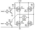
I need to amplify the signal and for that I was told to use a mosfet instead of a transistor.
I was also given this pic
2980211300_1428075408.png


Now, what I don't understand is:
- Where is the +5v source coming from? Do I need it?
- What does it mean when the capacitor is curved? Google says it doesn't matter
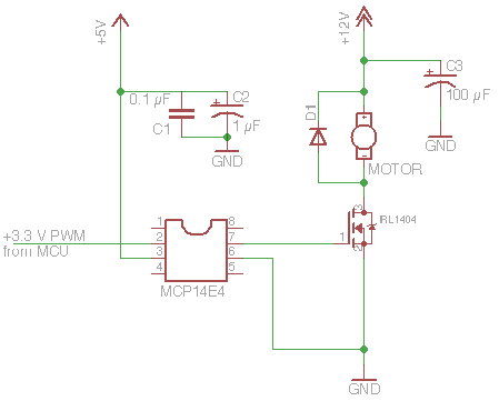
- Do I need 2x mosfets in order for this to work? I'm thinking of the MCP14E4 and the IRL1404.

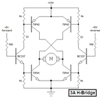
I also want to be able to change directions. In fact, this is essential for my application to work.
The control unit I have simply reverses the polarity and I was thinking that maybe I could put in a diode to enable the forward circuit and another diode for the backward circuit.

I'd also need to brake the motors, I thought of using a transistor and simply connecting it "backwards" so that when the controller is NOT sending out a signal, the motors wires will be shorted.

I would love to try and build this before getting the actual components but I can't seem to find a proper simulator for it. I think I clicked like 10 or 15 links on google.
 

What does it mean when the capacitor is curved?
Symbol for electrolytic cap.

For polarity reversal and breaking, you need a H-bridge (four transistor cicrcuit) instead of a single switch transistor.

You can have integrated H-bridge ICs like TI DRV8800 https://www.ti.com/product/drv8800
 

In fact, what I'm building is a miniature Motion Simulator like you see at funfairs. It's got 3 motors, but they are all a copy-paste of one another electric wise.
In order for it to work properly the motors need to go up and down continously.
I'm programming them using motor ports with built-in PWM funtion. These also have an H-bridge built-in but I cannot use them for obvious reasons.

That's why I wanted to make it work electronically only with the +9v/-9v PWM signals.
So you see, I cannot implement an H-bridge as it would require me to have 4 separate signals and I only have 2 wires. It just won't work.

Since Diodes block power from one direction, maybe I could just built 2 identical setups in parallel with the motor wires swapped on one of them, and attach a diode to each setup. This would work for up and down motions without shorting anything, right?

If I cannot get the break function I guess I'd manage, I could just set the output to be low enough that motor would be stalled. It would give a little more hassle programming-wise but it'd still work out.
 

I showed two discrete H-bridge circuits and here they are again. They are controlled with only 2 wires that you want. When one input wire goes high then the motor runs forwards. When the other input wire goes high then the motor runs in reverse. When both inputs go high then the motor has a brake.

EDIT: Oh, instead of applying a brake you want to break the motor? Then apply a voltage that is much too high.
 

Attachments

  • h-bridge transistors.PNG
    h-bridge transistors.PNG
    12.3 KB · Views: 111
  • H-bridge-Mosfets.PNG
    H-bridge-Mosfets.PNG
    11.2 KB · Views: 123

Hmm, ok I see it now.
I assume that I should use the one with the mosfets right? It's fine by me, I won't have to get that many resistors then.
Speaking of which, are you sure that I need 10k for R1 and R2? And 1k for R3 and R4?
Is there a formula that I need to use in order to calculate the right size resistor or are the ones in the diagram good enough?
 

The 10k base resistors might have a value too high since your signal source is only 5V or a little less. The datasheets for most little transistors shows that they saturate well when the base current is 1/10th the collector current so use Ohm's Law to calculate them. The base and collector resistor values must be reduced if the PWM frequency is higher than 25kHz.
 

EDIT: Oh, instead of applying a brake you want to break the motor? Then apply a voltage that is much too high.
Isn't that the same thing?

Circuit.png

I just made this in MS Paint. I need to know if the transistors I need has to be able to withstand 2 Amps or not so that I can find a transistor and calculate R1/R2 resistor values. I should choose one that is lower than the calculated result right?
I assume that R3/R4 resistors are ok at 1k?

Also, I kinda need a formula to work with. I am a graduated electrician but I never really worked with advanced electronics, maybe for a single week at school or something. I know about ohm's law and all so yeah...

I thought that since the base current is 1/10th of the collector current I assume that there's gonna be 0,2 A over R1/R2. And if I divide 9v with 0,2 I get 45 ohms.
I don't know, it seems kinda off so please give me a formula.
 

Attachments

  • Circuit.png
    Circuit.png
    31.5 KB · Views: 89

Ok, so I've finally got the components and I assembled it all on a breadboard as the diagram I posted earlier before soldering anything permanently.

I cannot get it to work though, nothing is happening.

Mosfet, P: IRF9530PBF
Mosfet, N: IRFZ24NPBF
Trans, NPN: BD135-16
R1/R2: 10k
R3/R4: 1k

Apparently, my 12 VDC supply is only 9 VDC, and my signal is not 9VDC but 6VDC.
It should be mentioned that my ground rail is hooked onto the 9VDC supply as the 6VDC signal changes +/- sides. Shouldn't the 2 grounds be connected somehow?

I have an measuring device if you need me to measure anywhere. And yes, I'm certain that it's wired correctly.

I think it's the resistors that are too big, and I'd love to get some clarification on how to calculate it.
 

I got a DC motor that runs at 12v, Load 1,58A and Stalled 2A
My controller spits out a 9v PWM signal.

I want my DC Motor to work at 12v with the PWM signal from the controller, basically increasing the voltage by 3v and keeping the same attributes of the controller.

I cannot get it to work though, nothing is happening.
...
...

Apparently, my 12 VDC supply is only 9 VDC, and my signal is not 9VDC but 6VDC.

From the above to quotes, you seem to indicate the motor requires 12VDC @2A, however now you are attempting to drive it at only 9VDC.

It should be mentioned that my ground rail is hooked onto the 9VDC supply as the 6VDC signal changes +/- sides. Shouldn't the 2 grounds be connected somehow?

Yes, both the motor and H-bridge control signals need to share a common GND. The H-bridge requires a positive (high) signal on the control line depending on the direction you desire the motor to turn.
 

A brake stops a motor, car or bicycle. A break is when something is destroyed or when you relax at work for 10 minutes.
A DC electric motor has a brake when it is shorted which makes it a generator driving the short and it becomes difficult to turn.

The input of the NPN transistor will be destroyed if you feed it -9V (or -6V). The circuit should have signals that are only +9V (or +6V) and 0V.
 

Ok, so I just got a bit smarter now.
I've been trying to draw some diodes and more transistors onto my curcuit drawing but I can't seem to find a solution.

As you should know, the 6V signal changes polarity when changing the direction. So if I want it to go forward, I have +/- on the cable, and if I want it to go reverse, I have -/+ on the cable.

I think a diode from each of the the two signal wires connected to the R1/R2 resistors should cover the + side, but what about the - side?
Minus power won't run through a diode and I need it to be connected to a common ground right? (aka, 9V battery) How would I do this when the polarity changes?
 

Status
Not open for further replies.

Part and Inventory Search

Welcome to EDABoard.com

Sponsor

Back
Top