Welcome to our site! EDAboard.com is an international Electronics Discussion Forum focused on EDA software, circuits, schematics, books, theory, papers, asic, pld, 8051, DSP, Network, RF, Analog Design, PCB, Service Manuals... and a whole lot more! To participate you need to register. Registration is free. Click here to register now.
I think it will be effect on output at input more than 30-40volt according to R1 & R2 amounts. Vr2 = Vout-Vz thus we have approximately Vout-Vz + 1.25 at output
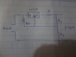
The z-diode has been placed to pass overvoltages to the output, trying to prevent breakdown of the regulator. The effect depends on the output load characteristic. If the load can tolerate surges, the circuit may be helpful. Otherwise it reduces the safe input voltage.
Similar to FvM, I suspect it's for protection, but to protect against low output voltage rather than high input voltage.
Imagine we have a circuit with unregulated input = 60V, regulated output = 40V. That should be OK because there's only 20V across the LM317.
However if there is a capacitor between output and ground, then there is a problem at switch-on. Without the zener, the voltage across the LM317 will initially be 60V, before the capacitor charges up.
However if there is a capacitor between output and ground, then there is a problem at switch-on. Without the zener, the voltage across the LM317 will initially be 60V, before the capacitor charges up.
Describes a case of possible failure. The initial capacitor voltage will be still zero, forcing the LM317 into current limit. Pulling the sense terminal up by a zener diode can destroy LM317 and zener diode immediately.
A bit of an odd circuit - the LM317 output is connected to the output via R1, not directly, so there'd be some current limiting. I wonder about HF stability if there's a cap at the output though.
This site uses cookies to help personalise content, tailor your experience and to keep you logged in if you register.
By continuing to use this site, you are consenting to our use of cookies.