Vermes
Advanced Member level 4

It is an interesting device – voltage transformer which is commonly used in electroenergetic networks to measure one phase voltage values on medium or high voltage lines.
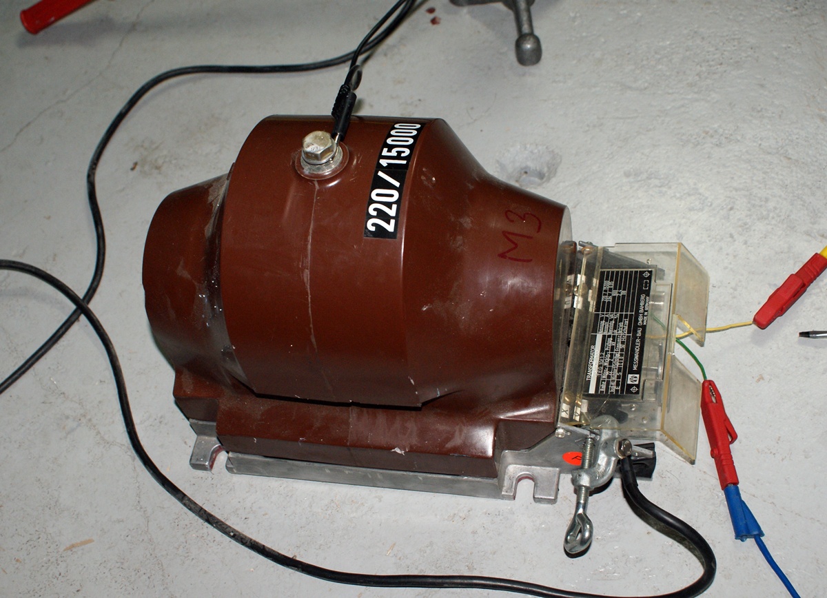
Such voltage transformer works identically as an ordinary transformer. Voltage from line WN passes to the primary winding which is very well protected and has a large number of turns. This causes that the voltage on the secondary winding (which has a smaller number of turns) is low. This voltage can be easily fed to the meters and thanks to proper scaling, the measurements can be performed in a safe way. Voltage transformers are mounted on poles very close to the line, so the voltage signal of small values is supplied to the building control or other control-measurement devices.
This transformer was adapted to measuring voltages in medium voltage networks with values of 15kV, and the the output of the secondary winding (at the value on the primary winding) should have 220V. Let's imagine that you change the winding and replace the secondary with the primary one.
Now, use the adjustable autotransformer as a choke. Connect the transformer in series through the primary winding of the autotransformer and short the secondary winding. Next, increase the autotransformer's power, controlling the flowing current at the same time. That will cause increase of the current value in the transformer's circuit. At 10% of power, the maximum power of the transformer (2,5kW) will be exceeded.
However, as you can see in the above pictures, you can test the voltage transformer at a primary winding level of 10A. Now it is time for you to examine the components of your device.
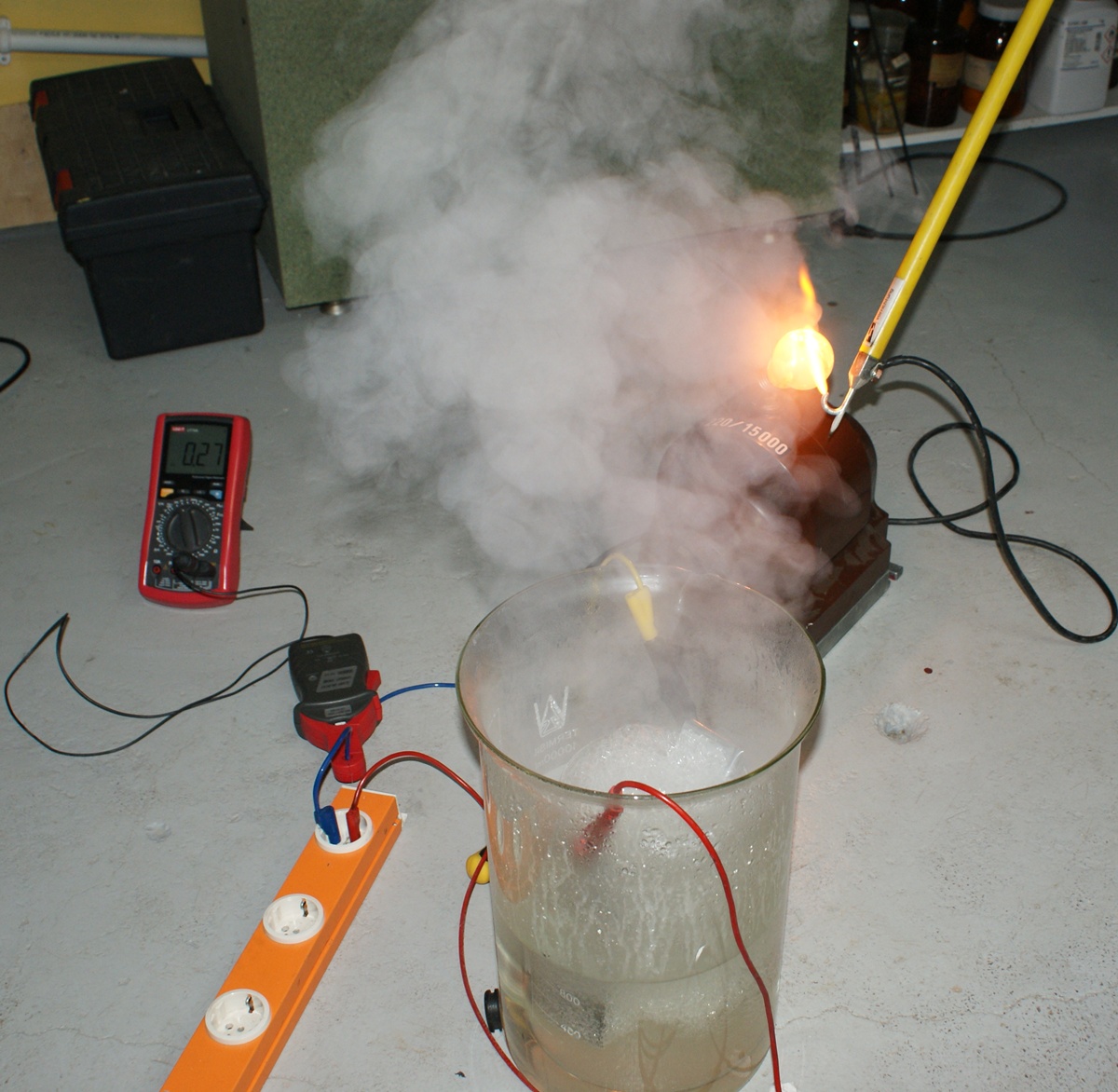
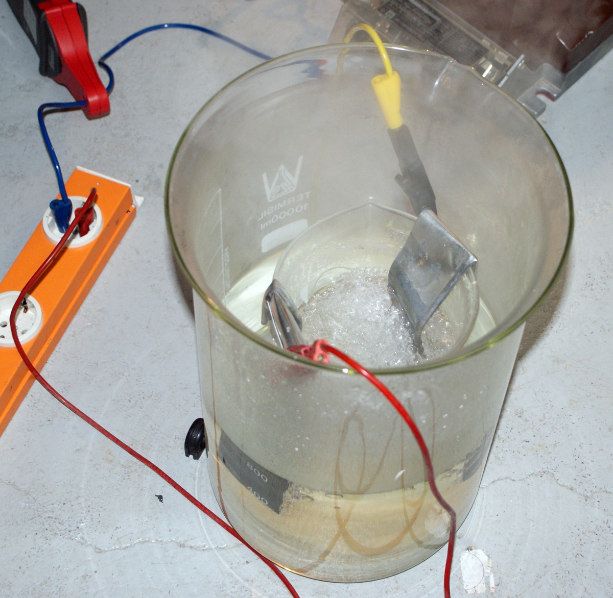
Instead of autotransformer with limited range of power, you can use two metal electrodes immersed in water, to which you should gradually pour saturated salt solution. Current clamps should be put on the cable and salt solution added gradually using a pipette. Then you can observe the current increase. The above picture on the left shows the behavior of the power regulator at a current of 27A.
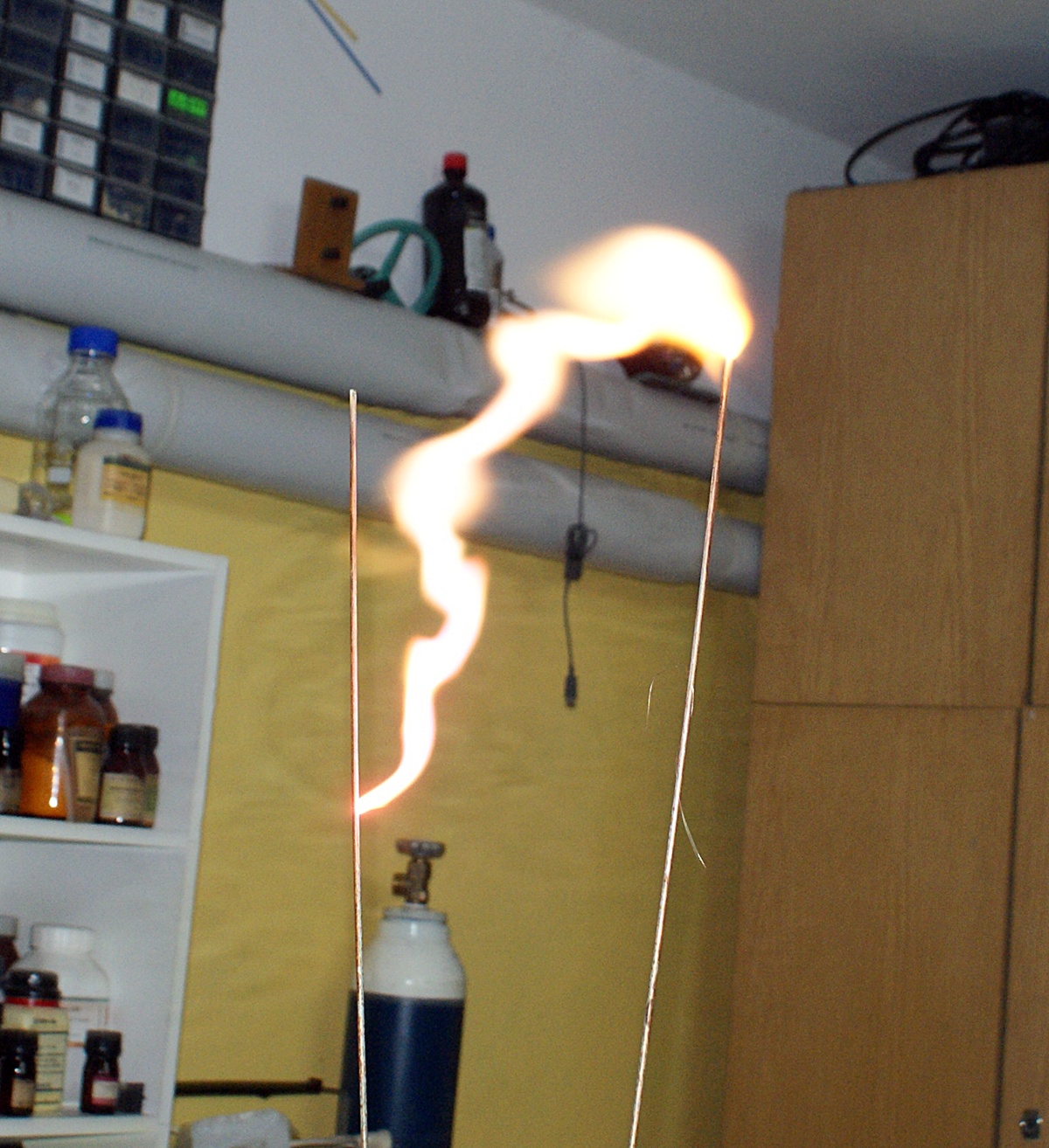

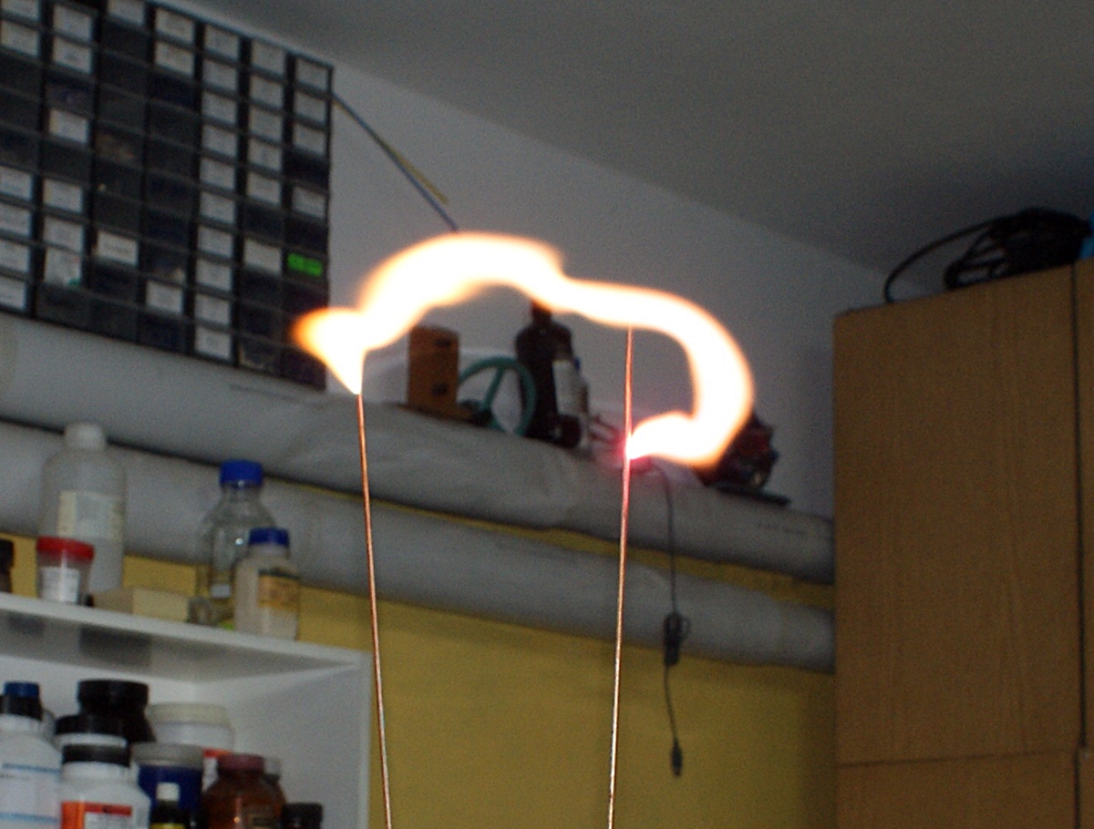
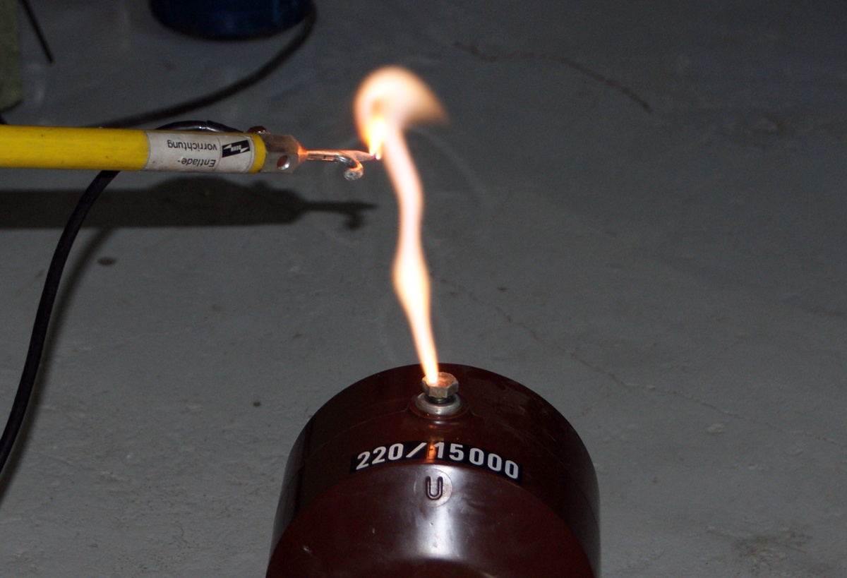
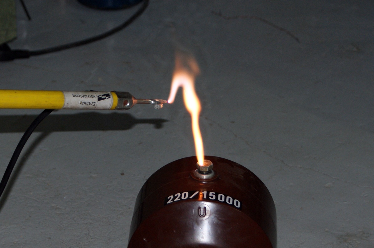
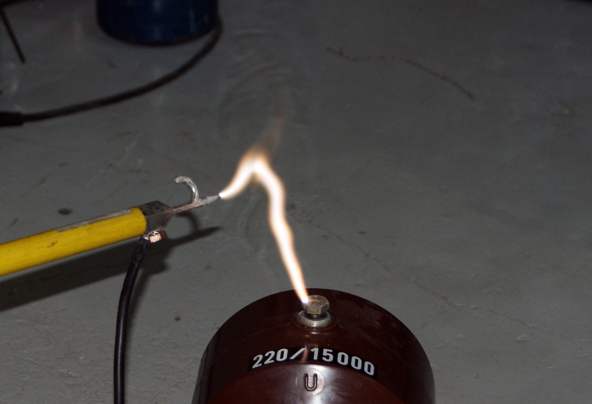
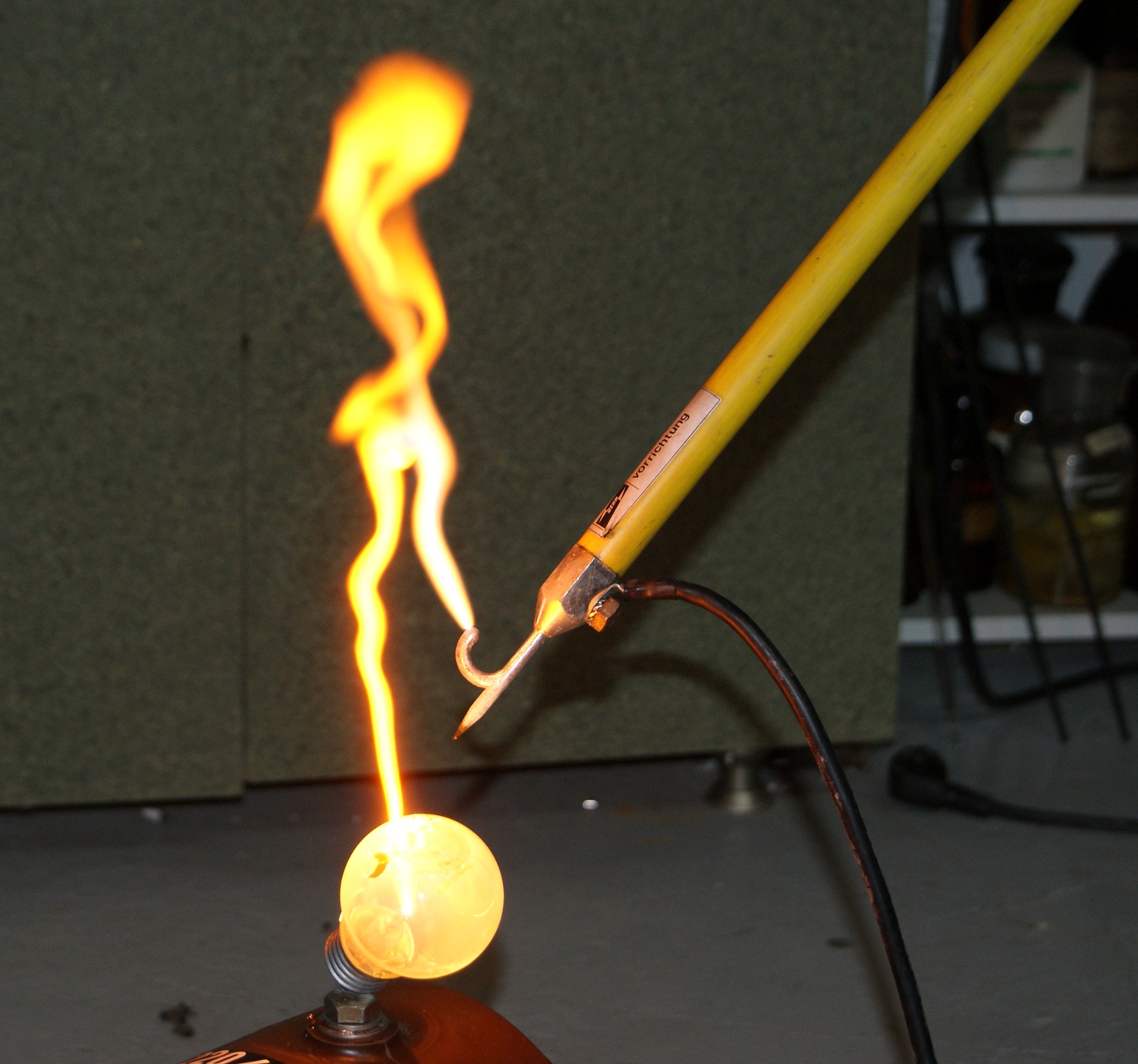
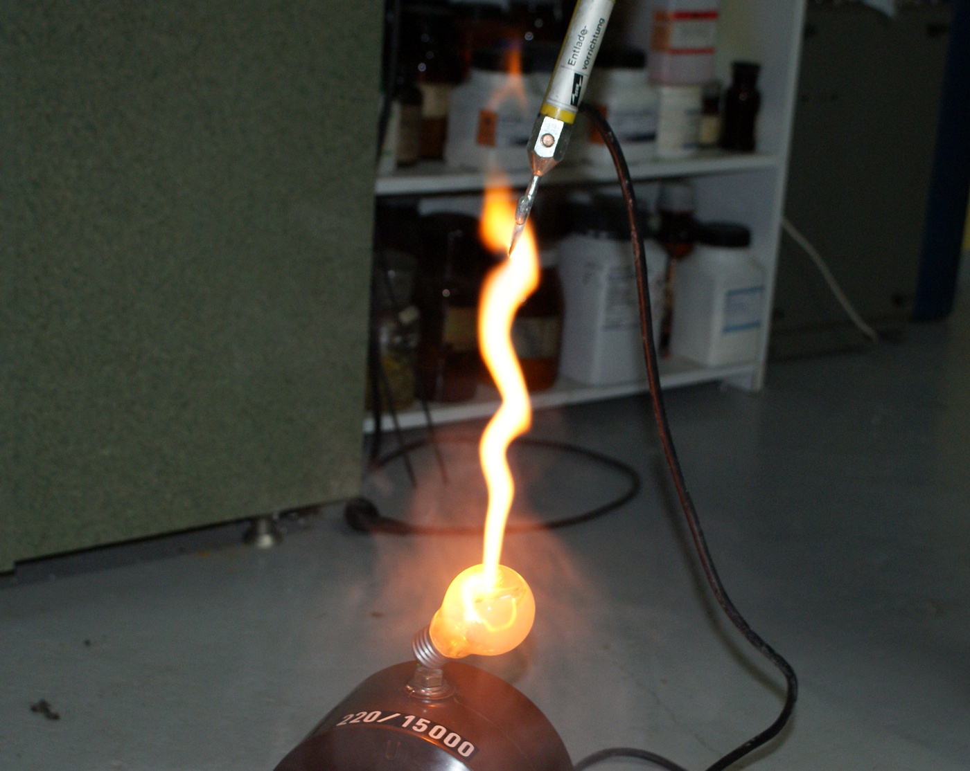
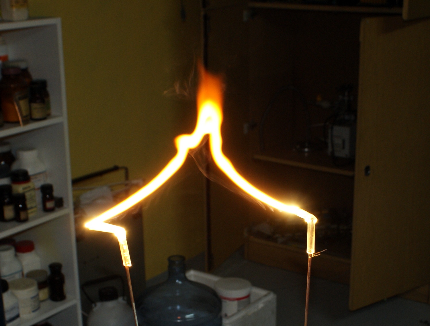
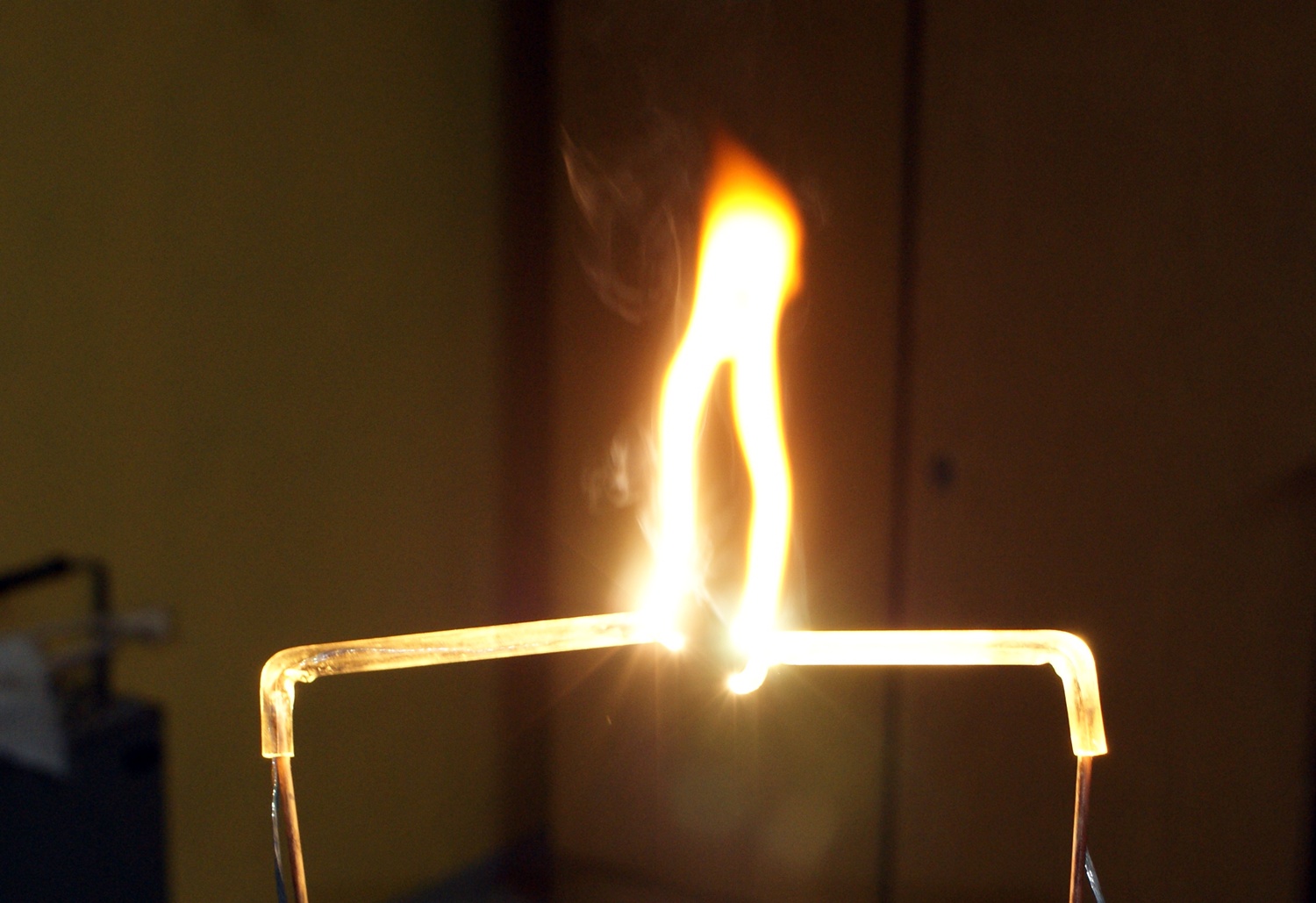
Pictures above show the effects of arc discharges on Jakubow's ladder. The electric arc lights up at the bottom and goes to the top, where it bends into a bow and extinguishes with a *****. The pictures also show how much heat is emitted – by observing the light refraction on hot air in some places.
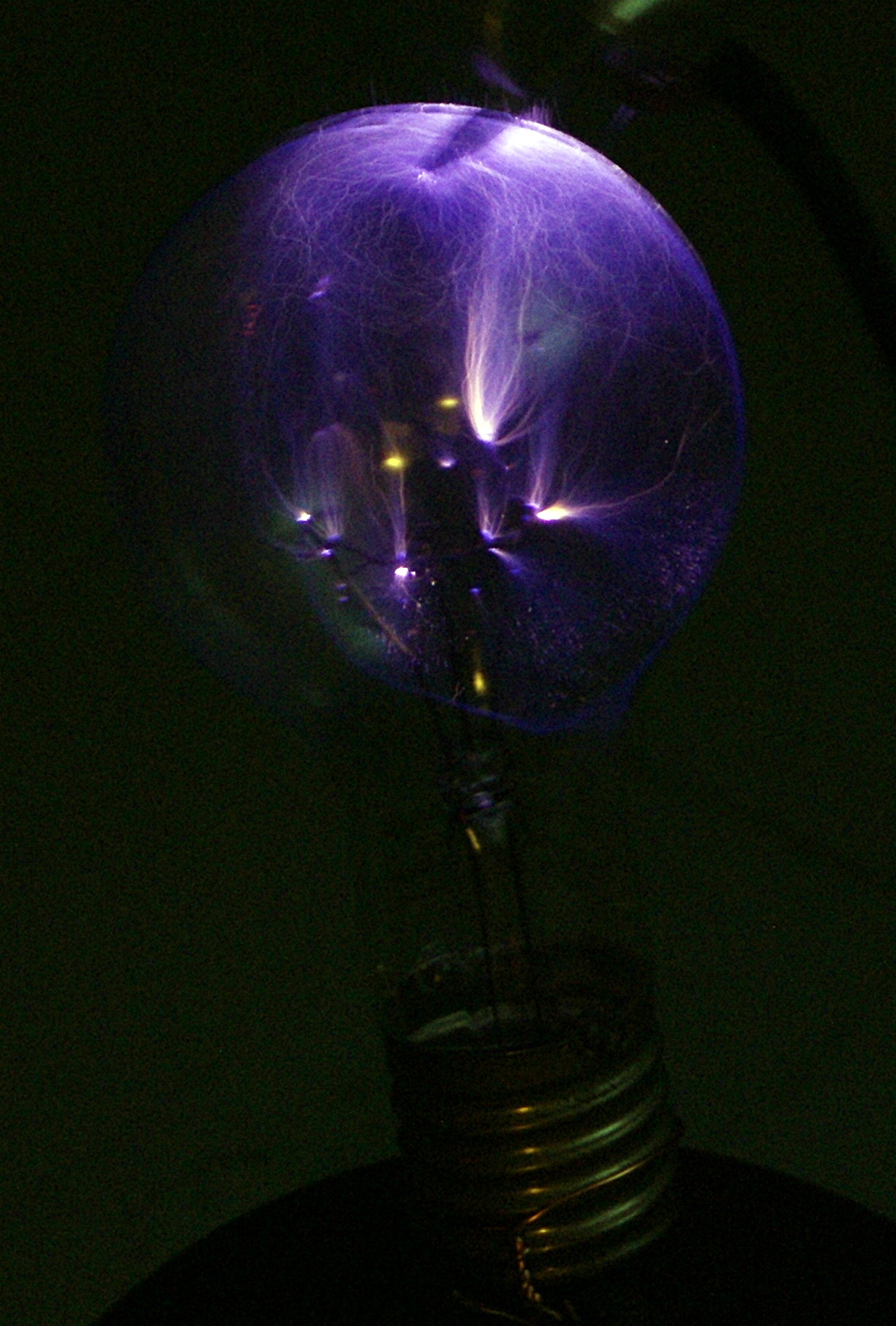
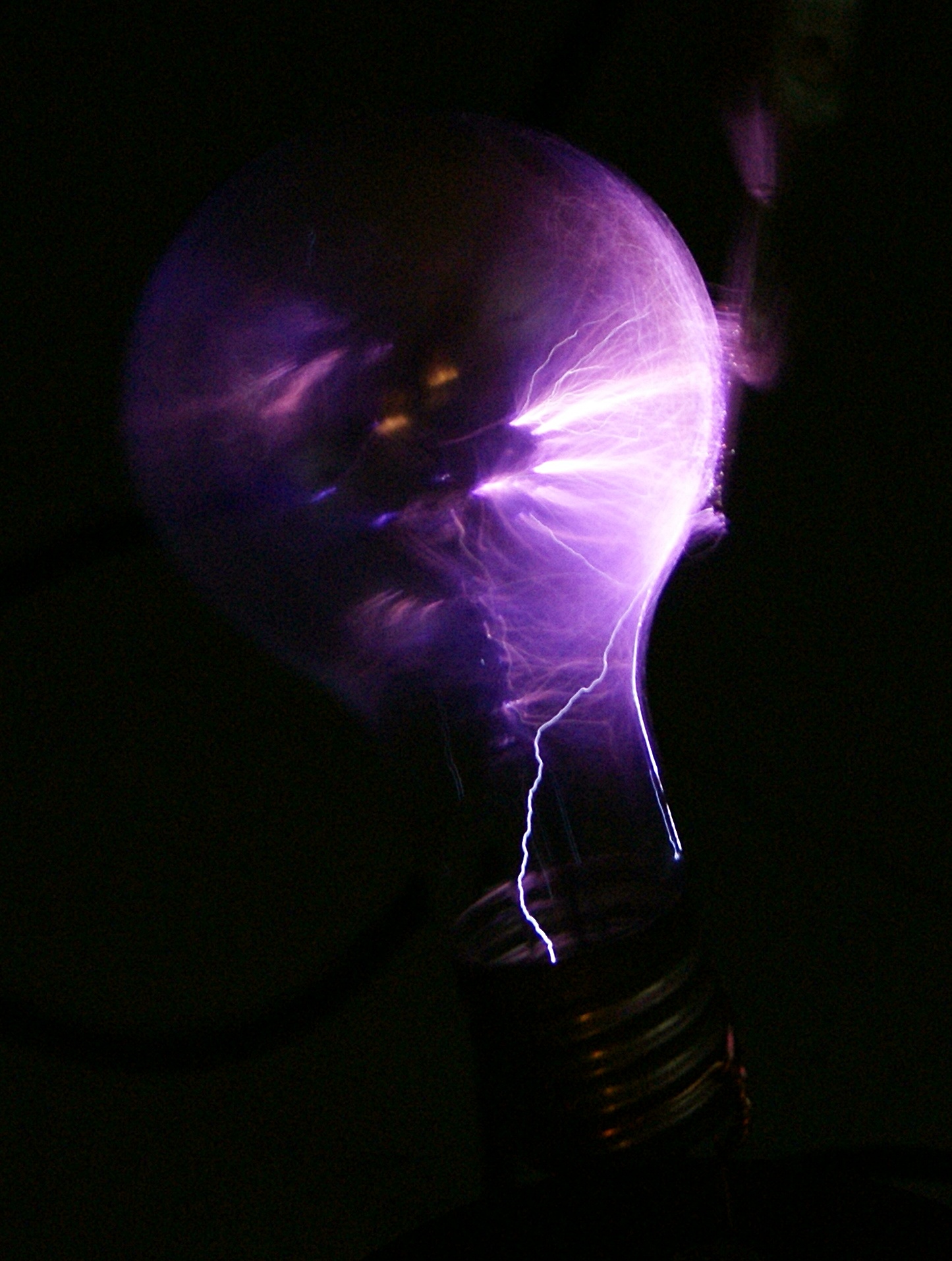
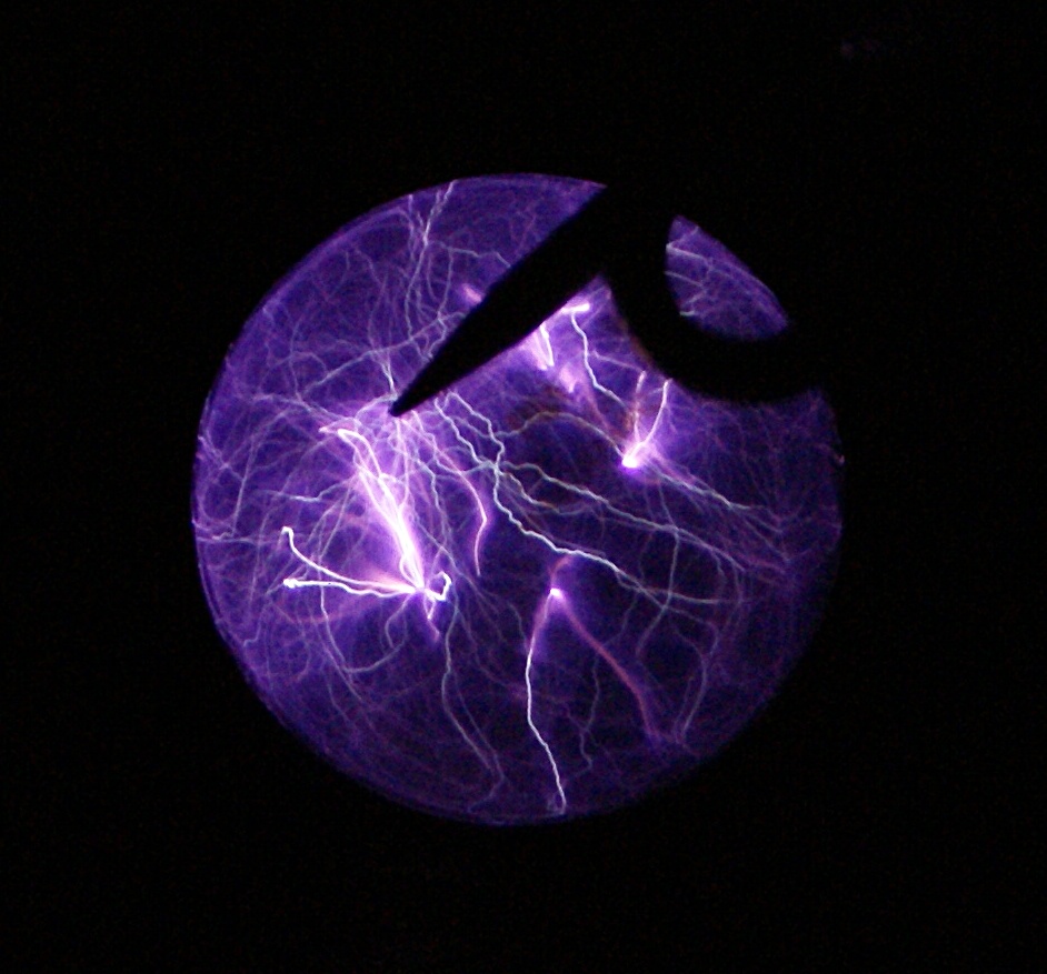
Above you can see the presentation of visual effects during discharges in a bulb.
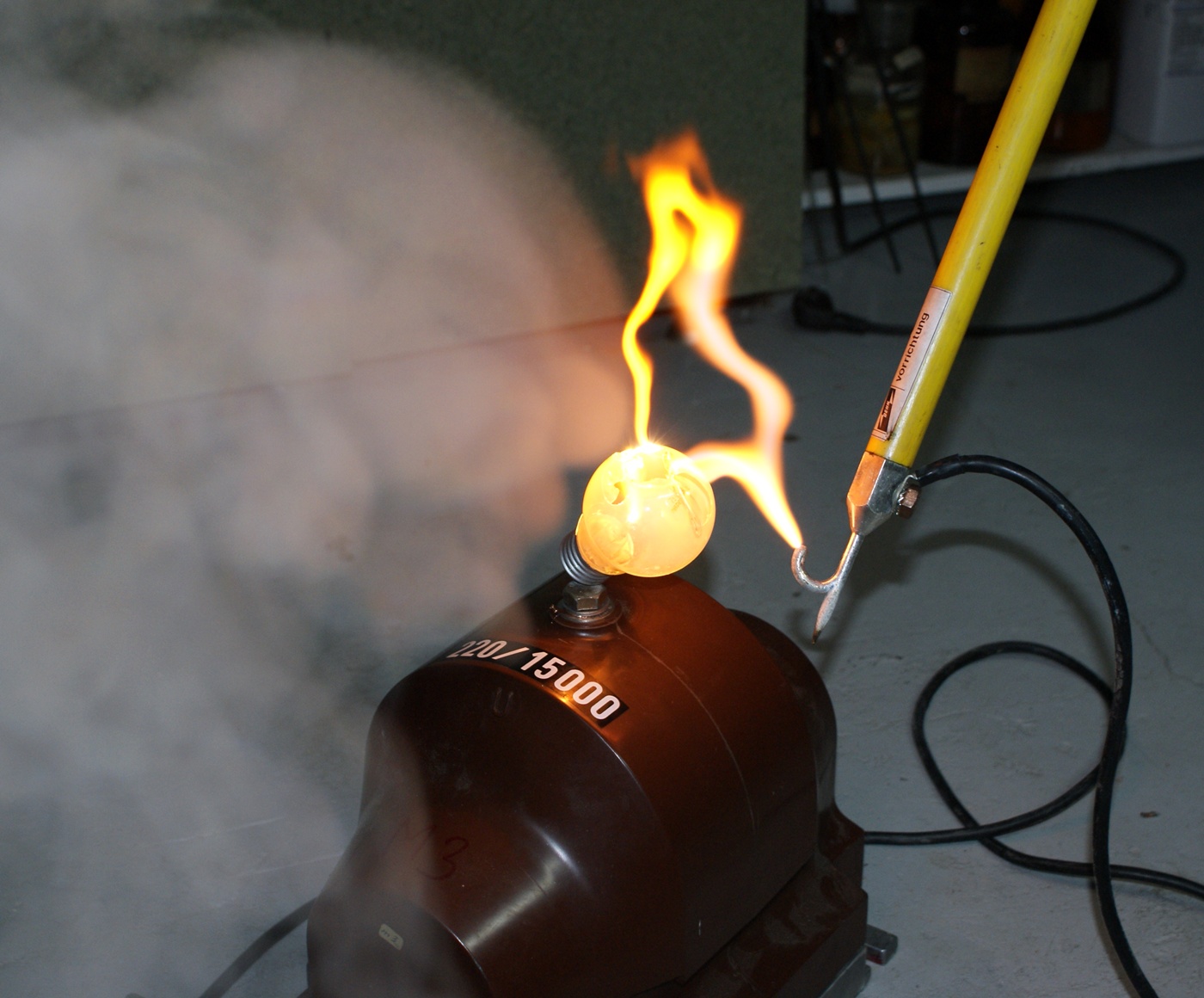
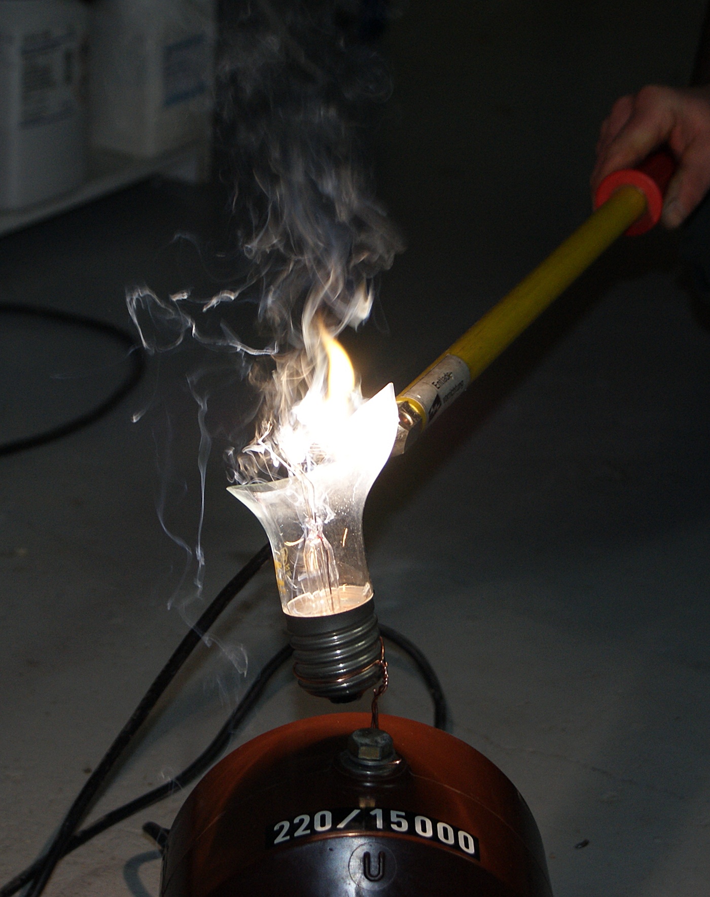
Tests which ended with breaking the bulb.
And there are some pictures of discharges in a glass pipe.
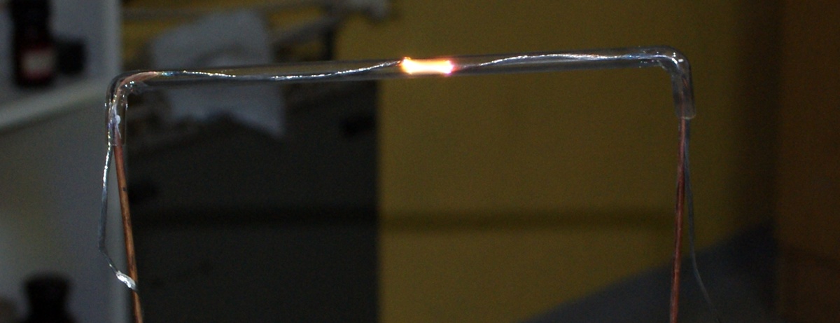
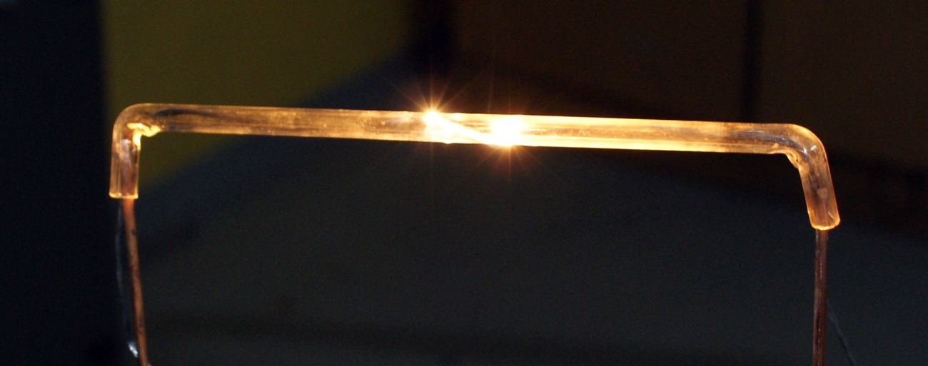
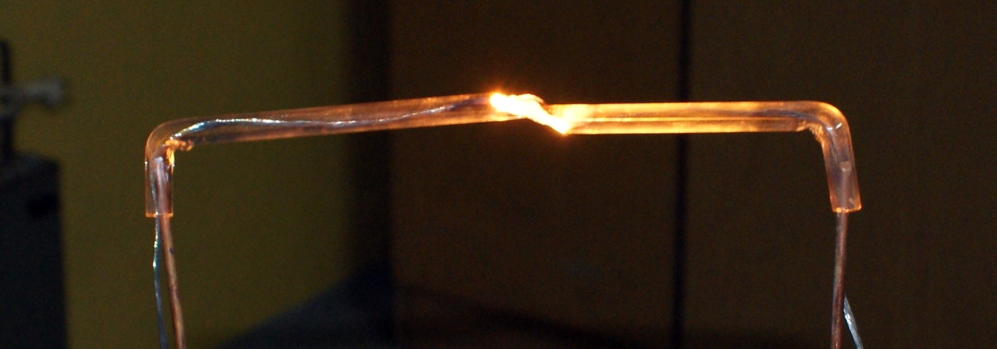
The transformer does not heat at all, even while receiving 7kW. This can be seen in experiments involving glass which starts melting.


Remember that such experiments should not be carried out by a beginner and inexperienced person – remember that voltages involved in this design can be harmful to your health and life!
Link to original thread - Przekładnik napięciowy w roli źródła wysokiego napięcia dużej mocy