Continue to Site

Welcome to EDAboard.com

Welcome to our site! EDAboard.com is an international Electronics Discussion Forum focused on EDA software, circuits, schematics, books, theory, papers, asic, pld, 8051, DSP, Network, RF, Analog Design, PCB, Service Manuals... and a whole lot more! To participate you need to register. Registration is free. Click here to register now.

[SOLVED] Voltage indicator - LED

Status
Not open for further replies.

Linspire

Full Member level 5
Joined
Sep 1, 2011
Messages
303
Helped
1
Reputation
2
Reaction score
1
Trophy points
1,298
Location
M'sia
Activity points
3,279
Hi,
I want to design a simple voltage indicator LED for my integrated circuit PIC18F4520.
Let say 5V will light up the green led to indicate full battery,
where as below 4.5V will light up red led to indicate low battery.
So far, what I can think is using voltage divider.
Any better solution ?
Or someone can guide me ?


Regards
Linspire
 

I want to design a simple voltage indicator LED for my integrated circuit PIC18F4520.

No way to call this simple circuit (why complicate this easy circuit with uC?), and such purpose of this uC is waste.


This circuit can be simple only with few parts, and no uC.
 

1.what say about using a adc for this kind of situation..i.e. set a ref. voltage and make out the code for 4-5 leds..
2.what say about using a bar graph led for this...it may also appear gud...
 

No way to call this simple circuit (why complicate this easy circuit with uC?), and such purpose of this uC is waste.


This circuit can be simple only with few parts, and no uC.

I mean make a simple circuit for showing batteries voltage which supply to PIC.
But how would really design it ?

Linspire
 

and yes, u may also op amps for this.... no need to use uC...
 

1.what say about using a adc for this kind of situation..i.e. set a ref. voltage and make out the code for 4-5 leds..
2.what say about using a bar graph led for this...it may also appear gud...

I have thinking of ATD, however my ATD's reference will based on the batteries source, which mean when batteries voltage drop down, the value of ATD will be different yields inaccurate indicator of voltage level.
Bar graph led ?
How to make this bar graph led ?

Linspire
 

Bro, i have never used it myself
bt i have seen people using it as a vlotage indicator...

Have a luk at youtube regarding d same...
You may make one of its kind using a voltage dividr and op amps..
 

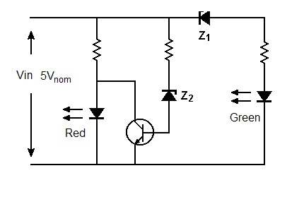
This will do what you want.

Try a 5V1 for Z1 and a 3V9 for Z2. If a 5V1 is too high try a 4V7 in series with a germanium diode.


5Vsensor.gif
 

This will do what you want.

Try a 5V1 for Z1 and a 3V9 for Z2. If a 5V1 is too high try a 4V7 in series with a germanium diode.


5Vsensor.gif

Well, my green led use quite high voltage to light up the LED.
5V1, 3V9 are zener model no. ?


Linspire
 

Linspire said:
I have thinking of ATD, however my ATD's reference will based on the batteries source, which mean when batteries voltage drop down, the value of ATD will be different yields inaccurate indicator of voltage level.

I do not use pic, but I suppose it must have an internal voltage reference. AVR has an 1.1V or 2.56V internal reference to be used for cases like that.

Linspire said:
I mean make a simple circuit for showing batteries voltage which supply to PIC.

Furthermore, if you have a battery to supply your MCU, then why waste battery's energy on a led indicator? Keep the led off and when the battery falls below a specific voltage level, do something with the LED (let's say keep it off for 5 seconds and on for 200ms). Finally, you could choose a proper resistor to create a led current that will light the led, but as much as the human eye needs to see it during daytime or inside an enviroment with other lights on. In this way you will save battery life and indicate low battery when needed.
 
Last edited:

Well, my green led use quite high voltage to light up the LED.
Yes of course, a silly oversight on my part. Use a 2V7 zener for Z1 and don't put a germanium diode in series.

5V1, 3V9 are zener model no?
No, they're zener voltages. Model numbers will depend on the manufacturer. Search the net for "zener diodes" and you will find many links to stockists and they will list zener voltages vs model numbers.
 

Furthermore, if you have a battery to supply your MCU, then why waste battery's energy on a led indicator? Keep the led off and when the battery falls below a specific voltage level, do something with the LED (let's say keep it of for 5 seconds and on for 200ms). Finally, you could choose a proper resistor to create a led current that will light the led, but as much as the human eye needs to see it during daytime or inside an enviroment with other lights on. In this way you will save battery life and indicate low battery when needed.

Are you trying to say the LED blinking will be turn on by a signal sent from the microcontroller.


Linspire
 

Linspire said:
Are you trying to say the LED blinking will be turn on by a signal sent from the microcontroller.

Yes, since the MCU is there, why not use it like that?
 

The problem with the suggested analog (z-diode, transistor, LED forward voltage based) solutions is, that they have indistinct and temperature dependent thresholds and are additionally affected by type variations. They won't give much pleasure, I fear.

Utilizing the uP for voltage discrimination and selective display is basically a good idea, supposed it has free resources for this purpose. The problem of missing reference voltage can be easily overcome. At minimum, you can supply a zener diode stabilized voltage to an AN pin and measure VCC indirectly ( Vcc = Vref*1024/ADCvalue). Ultimately, use a stable shunt reference.

GHi, FvM, glad to see you here.
Erm, you show some schematic diagram ?
How am I going supply to zener diode as Vref; or you saying using voltage drop of zener diode (0.7V) ?

Linspire
 

No, use a 3.3 or 3.9 V zener diode supplied by a series resistor. It will be still temperature dependent to some extent.
 

What'd stable shunt refer to ?


Linspire
 

A stable shunt reference would be e.g. LM385-2.5. Also 3-Terminal references like MCP1525 can be used, of course.
 

An Adjustable Precision Zener Shunt Regulator would also be an option
**broken link removed**

Alex
 

Status
Not open for further replies.

Similar threads

Part and Inventory Search

Welcome to EDABoard.com

Sponsor

Back
Top