Continue to Site
Follow along with the video below to see how to install our site as a web app on your home screen.
Note: This feature may not be available in some browsers.
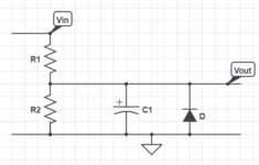
this is not generally true. it was for the PWM and for 0.1% ripple.Klaus said aim for a low pass filter fc = 1/1000.