Continue to Site

Welcome to EDAboard.com

Welcome to our site! EDAboard.com is an international Electronics Discussion Forum focused on EDA software, circuits, schematics, books, theory, papers, asic, pld, 8051, DSP, Network, RF, Analog Design, PCB, Service Manuals... and a whole lot more! To participate you need to register. Registration is free. Click here to register now.

Voltage adjustment in cyclic voltammetry circuit

Status
Not open for further replies.

ecaits1

Newbie
Joined
Feb 9, 2022
Messages
2
Helped
0
Reputation
0
Reaction score
0
Trophy points
1
Activity points
21
FINAL CIRCUIT_Description.jpg

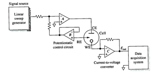
This is a circuit of cyclic voltammetry in which all three electrode i.e. WE (Working Electrode), CE(Counter Electrode) & RE (Reference Electrode) are dipped in electrolyte solution.

The source voltage is -1V to +1V (mentioned in circuit) but generally we are using -0.2V to +0.6V as scanning voltage. During scanning (-0.2V to +0.6V), I have measured the voltage between working electrode (WE) and reference electrode (RE) which is -0.4 to +0.8V (approx.) which should be -0.2V to +0.6V and this is happened due to electrolyte (solution resistance).

The circuit may need to improve by taking feedback from WE & RE to make it exact -0.2V to +0.6V.

I want few suggestion for circuit improvement.
 

Hi,

there are a lot of issues ... or maybe i don´t understand how you expect it to work.

* no power supply and no power supply capacitors. Yes, I know that some simulation run without them, but a real circuit will have problems..
* No naming of the parts makes it difficutl to discuss a circuit.
* 100uF directly connected at the ouput of the most right OPAMP. Usually OPAMPs are not made to drive that large capacitance.
* non_inverting input to most right OPAMP is named with "1V ref for shifting".
But it is not 1V, it rather is "PIN3_DAC / 5" --> it shifts with PWM.
* RE input has no ESD protection.... it´s easy to kill the OPAMP by handling of the electrodes.
* while CE and WE are less prone for ESD problems, I still recommend to add ESD protection.
* lower_LT1097 has no local feedback. You risk oscillation and noise pickup.
* add capacitors to the DC nodes to stabilize them and reduce noise.

The overall function is not clear to me.

Klaus

Hello Klaus,

I have not mentioned the power supplies in op-amps otherwise +/-12V is provided.
100uF op-amp is not connected direct to op-amp. The output of op-amp is given to ADC module.
1V reference IC is used for voltage shifting from (0V to 5V) range to (-1V to +1V) using voltage divider method.
RE is just reference electrode to provide the fix reference voltage for WE(working electrode) so in this application, i think no need of ESD protection and same way for CE & WE.
For, lower_LT1097 has no local feedback but it has feedback through electro-chemical cell. You can suggest for that.

The main issue is that the voltage between WE & RE should be same to voltage of linear sweep generator.
If the voltage of linear sweep generator is -0.2V to +0.6V then voltage between WE & RE is approx. -0.4 to +0.8V (approx.)
 

Attachments

  • CV Circuit.png
    CV Circuit.png
    34.5 KB · Views: 76

Status
Not open for further replies.

Similar threads

Part and Inventory Search

Welcome to EDABoard.com

Sponsor

Back
Top