Continue to Site

Welcome to EDAboard.com

Welcome to our site! EDAboard.com is an international Electronics Discussion Forum focused on EDA software, circuits, schematics, books, theory, papers, asic, pld, 8051, DSP, Network, RF, Analog Design, PCB, Service Manuals... and a whole lot more! To participate you need to register. Registration is free. Click here to register now.

[SOLVED] VNA S Parameters Measurements - Insertion and Return loss

Status
Not open for further replies.

Nia11

Newbie level 5
Joined
Jun 14, 2016
Messages
10
Helped
0
Reputation
0
Reaction score
0
Trophy points
1
Location
Paris,France
Activity points
87
small_ac_1.png

Hello,

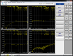
I am using keysight M9370A VNA, I just want to clear my doubts on VNA plots, I have attached the picture of VNA S parameters plots of an attenuator of 16dB ( connected to the ports of the VNA) with this post.

From the picture, It is clearly seen that the plots are in logmag format.

S11 plot - for example, at 2 GHz, it is -22.14 dB. So we can take Return loss, RL (at input)=-22.14 dB ( RL should be +VE, so we can take RL = 22.14dB ).

S21 plot - The value @ 2GHz is -14.24 dB, so we can take Insertion loss, IL = -14.24dB @ 2GHz. And Gain = - Insertion Loss. Therefore, Gain= 14.24 dB.

So my question is that the above measurements are correct or wrong?, because in the case of VNA S parameter measurements ,each article says different opinion. It was just confusing.

Is the VNA Logmag format shows just the value of S11 or S21(in the picture), and we have to calculate the Return loss and Insertion loss with the formulas below.?

RL = -20logǀS11ǀ dB
IL= -20logǀS21ǀ dB

So substituting the values of S11 and S21 we obtained from the picture, S11= -22.14dB and S21=-14.24dB

We get, RL = -26.9 dB = 26.9 dB.
IL= -23 dB and therefore Gain = 23 dB.

From the above two methods which one is correct, Could anyone please help me to clear this confusion. Thank you in advance.
 

S11_dB=20*log10(abs(s11))
S21_dB=20*log10(abs(s21))

RL=-S11_dB
IL=-S21_dB

So RL=22.14dB, IL=14.24dB
 
  • Like
Reactions: Nia11

    Nia11

    Points: 2
    Helpful Answer Positive Rating
S11_dB=20*log10(abs(s11))
S21_dB=20*log10(abs(s21))

RL=-S11_dB
IL=-S21_dB

So RL=22.14dB, IL=14.24dB


Thank you. And If IL = 14.24dB means, then Gain will be -14.24dB right?. And I used an attenuator of 16dB, so gain should be 14.24dB ( not -14.24dB)?
 

  • Like
Reactions: Nia11

    Nia11

    Points: 2
    Helpful Answer Positive Rating
I should point out one thing..
Either your VNA calibration is not well done or your device is oscillating.
 

Hi,
Maybe, but I used ECal module for calibration so i dont think it was due to calibration. Are you telling that the result plot is not accurate?
 

but I used ECal module for calibration
so i dont think it was due to calibration.
Are you telling that the result plot is not accurate?
I don't think your DUT is oscillating.

I suspect "Thru" calibration.
Your measurement frequency range is 300kHz~4GHz at most.
However, your S21 and S12 result are too far from -16dB.
Behavior of S11 and S22 have to be same. But they are different.

Show me details of your DUT.
Isn't it a SMA type attenuator of 16dB ?

See the followings.
https://www.minicircuits.com/pdfs/BW-S15W2+.pdf
https://www.minicircuits.com/pages/s-params/BW-S15W2+_GRAPHS.pdf
https://www.minicircuits.com/pages/s-params/BW-S15W2+_VIEW.pdf
 
Last edited:

Attenuators Specifications: Attenuator 16 dB
@ 30 MHz - 15.0 dB
@ 1 GHz - 14.60 dB
And it is not an SMA type, BNC type attenuator.
 

And it is not an SMA type,
BNC type attenuator.
I think your ECal is 3.5mm type.
And I think your cable connector from VNA is APC3.5.
After ECal, how to connect calibrated 3.5mm connector to BNC ?

If you simply use SMA-BNC conversion connector, it causes large error.
 
Last edited:

I think your ECal is 3.5mm type..

3.5mm type?, No actually it is an N type connector.
And I think your cable connector from VNA is APC3.5.
After ECal, how to connect calibrated 3.5mm connector to BNC ?

If you simply use SMA-BNC conversion connector, it causes large error.

I used atennuator as a reference for my testing, actually I am doing measurements with Antennas. Thank you so much for taking your time to answer me.
 
Last edited by a moderator:

Standard BNC Connectors don't work at 4GHz. Max. frequency for this type is 1GHz.
 

Status
Not open for further replies.

Part and Inventory Search

Welcome to EDABoard.com

Sponsor

Back
Top