Continue to Site

Welcome to EDAboard.com

Welcome to our site! EDAboard.com is an international Electronics Discussion Forum focused on EDA software, circuits, schematics, books, theory, papers, asic, pld, 8051, DSP, Network, RF, Analog Design, PCB, Service Manuals... and a whole lot more! To participate you need to register. Registration is free. Click here to register now.

[PIC] virtual terminal in proteus interfaced with pi18f46k22

Status
Not open for further replies.

Livingston

Full Member level 2
Joined
Nov 26, 2007
Messages
129
Helped
3
Reputation
6
Reaction score
1
Trophy points
1,298
Location
Chennai-India
Activity points
2,104
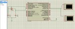
I have a problem with virtual terminal of proteus 8. I wrote a code in mikroc PRO for pic. The code was to recieve data at 19200 baud rate and parse the string so that i read 8 bytes. I have used a circular buffer, you can find how the circular buffer works from this link https://leap-embedded-system.com/?p=79 . i have used an interrupt based program since i shouldnt miss any received data. The problem comes when i test this with the virtual terminal of proteus. i give input to my pic from virtual terminal and observe the ouput through another virtual terminal. When i give input i pasted 6 strings and the virtual terminal just transmits 4 and a half strings and i am getting 4 outputs. when i paste only 4 strings or less to the terminal i get outputs for all the strings sent. Also to mention when i work at baud rates of 4800 or 2400 i get outputs for any number of strings.
i tested this for a simple program which uses inteerupts to echo a character, even then the virtual terminal limits the numebr of chars entered by stopping somewhere in the middle.

Is this a problem of virtual terminal ? i should strictly follow a baud rate of 19200!
I am pasting the code below ,

Code C - [expand]
1
2
3
4
5
6
7
8
9
10
11
12
13
14
15
16
17
18
19
20
21
22
23
24
25
26
27
28
29
30
31
32
33
34
35
36
37
38
39
40
41
42
43
44
45
46
47
48
49
50
51
52
53
54
55
56
57
58
59
60
61
62
63
64
65
66
67
68
69
70
71
72
73
74
75
76
77
78
79
80
81
82
83
84
85
char rxchar;  //variable for storing data from UART
 int i = 0, flag = 0,count=0,j=0,msgs=0;  // array counter and flag to write once the desired pattern is read
 char buf[1025];   // array to store the received charaters
 char *rc_ptr,*tx_ptr;
 char output[15],testbuf[2]; //array to write data to tx
 enum{WAIT_FOR_1C,WAIT_FOR_6bytes,RECEIVING,MSG_RCVD} state=WAIT_FOR_1C;
 /*******************************************************************************/
void interrupt () {
  if (PIR1.RCIF) {     // test the interrupt for uart rx
     rxchar = UART1_Read();  //read a byte from UART
 
      switch(state){
               case WAIT_FOR_1C:   //wait till 1C is arrived
               if(j>1){
               j=1;
               testbuf[0]=testbuf[1];
               testbuf[j]=rxchar;
               j++;
                   if(strstr(testbuf,"1C")!=0){
                   j=0;
                   state = WAIT_FOR_6bytes;
                     }
               }
               testbuf[j]=rxchar;
               j++;
                   if(strstr(testbuf,"1C")!=0){
                   j=0;
                   state = WAIT_FOR_6bytes;
                         }
               break;
               case WAIT_FOR_6bytes:
                i++;
                if(i>=6){
                 i=0;
                 state=RECEIVING;
                }
               break;
               case RECEIVING:
 
               if(count==1024){
                  count=0;
                  rc_ptr=buf;
               }
               *rc_ptr=rxchar;
               rc_ptr++;
               count++;
               if(count%8==0){
               msgs=msgs+1;
               state=WAIT_FOR_1C ;
               }
               break;
  } // end interrupt
  }
  }
  /******************************************************************************/
void main () {
 ANSELA=0;
 ANSELC=0;
 TRISA=0;
 TRISC=0xC0;
 LATA=0x00;
 
 INTCON.GIE = 1;      //enable global interrupt
 INTCON.PEIE = 1;
 PIE1.RCIE = 1; //enable receive interrupt.
 UART1_Init(4800);
    rc_ptr=buf;
    tx_ptr=buf;
 while(1) {   // Begin endless loop
  // This section is where you tell the program what to do with the data once it
  // has all arrived
     while(msgs!=0){         //read all the messages
     
   strncpy(output,tx_ptr,8);   //copy 8 bytes from the buffer
   Uart1_Write_Text("DATA:");
   Uart1_Write_Text(output);
   Uart1_Write(13);              //new line char
   tx_ptr=tx_ptr+8;               // increment the tr_ptr to the next 8 bytes
   if( tx_ptr - buf ==1024){      //if tx_ptr reaches the end of buffer loop back to beginning
   tx_ptr = buf;
   }
   msgs=msgs-1;
      }
 } // end while
} // end main

 
Last edited by a moderator:

It's not a good practice to be using so complicated receiving interrupt routine (using 19 kBaud it is occuring on every 520 usec). Try to write a much simpler (shorter) IT routine and make almost all buffer manipulations/calculations in the main loop (not under interrupt since the buffer manipulations are time consuming).

Please zip and attach the full MikroC project (the DSN too but in Proteus v7.x if possible).
 
Last edited:

THANKS! zuisti. i even tried this with a shorter isr, which simply reads the byte and echos back. even for that case the virtual terminal in proteus stops taking chars after a certain length. i am attaching the zip file. sorry i couldnt get a dsn file. please make the connections from the picture. The crystal uses 8MHz .
 

Attachments

  • serialtest.zip
    62.5 KB · Views: 107
  • Capture.JPG
    Capture.JPG
    142.2 KB · Views: 145

Status
Not open for further replies.

Similar threads

Part and Inventory Search

Welcome to EDABoard.com

Sponsor

Back
Top