Continue to Site

Welcome to EDAboard.com

Welcome to our site! EDAboard.com is an international Electronics Discussion Forum focused on EDA software, circuits, schematics, books, theory, papers, asic, pld, 8051, DSP, Network, RF, Analog Design, PCB, Service Manuals... and a whole lot more! To participate you need to register. Registration is free. Click here to register now.

vhdl sram code not working

Status
Not open for further replies.

hithesh123

Full Member level 6
Joined
Nov 21, 2009
Messages
324
Helped
1
Reputation
2
Reaction score
1
Trophy points
1,298
Location
lax
Activity points
3,548
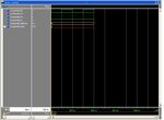
I tried to execute the vhdl code for clocked SRAM. When I simulate 'data' is unknown. output enable is low and chip select is also low.
It's declared as inout.
Code is same as pg. 144 in Mark zwolinski's book except for the clock.
Library IEEE;
use IEEE.std_logic_1164.all;
use IEEE.numeric_std.all;

Code:
Entity Sram64 is
  Port (address : in integer range 0 to 63;
    we, oe, cs, clk : in std_logic;
    data: inout std_logic_vector ( 7 downto 0)
  );
 end entity sram64;
 
 Architecture aone of Sram64 is 
 Begin
   
  process(clk, address, we, oe, cs)
   type ram_array is array (0 to 63) of std_logic_vector (7 downto 0);
   variable mem : ram_array;
   Begin
     --data <= (others =>'0');
     If  rising_edge(clk) then
       If ( cs = '0') then          -- chip is selected
         If (oe='0') then           -- Read operation (output enabled)
           data <= mem(address);
         elsif (we='0') then        -- write operation
           mem(address):=data;
         end if;
       end if;
     end if;
   end process;
 end architecture aone;
 

I guess that you are,trying to read before you written some data to sram.
 

you need to assign data to (others => 'z') as the default operation. That means data wont clash with the previously driven version of itself.

You also only need clk in the sensitivity list.

Code:
process(clk)
   type ram_array is array (0 to 63) of std_logic_vector (7 downto 0);
   variable mem : ram_array;
 Begin
   
   If  rising_edge(clk) then
     data <= (others =>'Z');
    
     If ( cs = '0') then          -- chip is selected
       If (oe='0') then           -- Read operation (output enabled)
         data <= mem(address);
       elsif (we='0') then        -- write operation
         mem(address):=data;
       end if;
     end if;
   end if;
 end process;
end architecture aone;

I assume this is just a simulation model, and not code that you intend to compile, because it will probably not synthesise to a ram on an FPGA.
 

If I make data <= (others =>'Z'); at the rising edge of the clock, data would be high Z at every clock cycle.

Yes, this is for simulation only. But why wouldn't it be synthesised in to a ram.
 

This couldnt be synthesised because you are using a tristated data port. There are no tristates internally and these would be converted to muxes. You might get lucky and get a ram, or you might not. Its best to follow the coding templates if you want your synthesisor to infer a ram.

---------- Post added at 16:16 ---------- Previous post was at 16:14 ----------

If I make data <= (others =>'Z'); at the rising edge of the clock, data would be high Z at every clock cycle.

Yes, this is for simulation only. But why wouldn't it be synthesised in to a ram.

Actually, it wouldnt, and would behave properly. The data assignment is overwridden if oe = '0', so then it is not assigned to all 'z'
 

This couldnt be synthesised because you are using a tristated data port. There are no tristates internally and these would be converted to muxes. You might get lucky and get a ram, or you might not. Its best to follow the coding templates if you want your synthesisor to infer a ram.


Is this why the RAM examples in XST user guide have separate ports for data in and data out?

So basically tristated ports cannot be synthesised?
 

Code is same as pg. 144 in Mark zwolinski's book except for the clock.
I already knew, that something may be missing if you say, it's code from a Mark Zwolinski's book. This time, it's
Code:
data <= (others =>'Z');
I assume, you already realized that the asynchronous RAM example must be converted to a synchronous one to become synthesizable. It's quite instructive to consider, why it has to be changed the way TrickDicky suggests, with the tri-state assignment in the clock edge sensitive code part.

I assume this is just a simulation model, and not code that you intend to compile, because it will probably not synthesise to a ram on an FPGA.
It's recognized by Altera Quartus as a RAM with succeeding tri-state buffer.
 

when I make data as high Z at the rising edge of the clock, should the data line tristate? But when i simulate, I still get unknown state, until I write something to data.
see sim waveform attachment.
 

Attachments

  • dataz.JPG
    dataz.JPG
    55.2 KB · Views: 90

I don't see how your testbench would be able to detect a 'Z' state of the device under test directly? The other question is how you drive the inout signal in your testbench.
 

I don't see how your testbench would be able to detect a 'Z' state of the device under test directly? The other question is how you drive the inout signal in your testbench.

data is made high 'Z' in the code itself.
In the test bench I just load a value to data, like data<="11110000";
 

can you post the testbench and the code for the UUT again?
 

can you post the testbench and the code for the UUT again?

uut code

Code:
Library IEEE;
use IEEE.std_logic_1164.all;
use IEEE.numeric_std.all;


Entity Sram64 is
  Port (address : in integer range 0 to 63;
    we, oe, cs, clk : in std_logic;
    data: inout std_logic_vector ( 7 downto 0)
  );
 end sram64;
 
 Architecture aone of Sram64 is
 
 Begin
   
  process(clk, address, we, oe, cs)
   type ram_array is array (0 to 63) of std_logic_vector (7 downto 0);
   variable mem : ram_array;
   Begin
     
     If  rising_edge(clk) then
       data <= (others =>'Z');
       If ( cs = '0') then          -- chip is selected
         If (we='0') then           -- write operation      
           mem(address):=data;           
         elsif (oe='0') then        -- Read operation (output enabled)           
           data <= mem(address);
         end if;
       end if;
     end if;
   end process;
 end aone;

test bench -

Code:
Library IEEE;
use IEEE.std_logic_1164.all;
use IEEE.numeric_std.all;
Entity sram64tb is
end sram64tb;
architecture tb of sram64tb is
component Sram64 is
  Port (address : in integer range 0 to 63;
    we, oe, cs, clk : in std_logic;
    data: inout std_logic_vector ( 7 downto 0)
  );
 end component;
signal we, oe, cs, clk : std_logic;
signal address : integer range 0 to 63;
signal data : std_logic_vector (7 downto 0);
Begin
  
  uut: sram64 port map ( we => we, oe=>oe, cs=>cs, clk=>clk, address=>address, data=>data);
    
    process  --clock generation process 
      begin
        clk<='0';
        wait for 100ns;
        clk<='1';
        wait for 100ns;
      end process;
      
      process
        variable data_byte : std_logic_vector(7 downto 0);
        begin
          cs<='1';
          we<='1';
          oe<='1';
          address<=0;
          wait for 400ns;
          cs<='0';
          address<=10;           -- write data to address 10
          data<="10101010";
          wait for 200ns;
          we<='0';
          wait for 200ns;
          address<=9;            -- Change address
          data<="00001111";
          wait for 200ns;
          we<='1';
          data<=(others=>'Z');
          wait for 200ns;
          oe<='0';
          wait for 200ns;
          address<=address+1;       -- go back to address 10
          oe<='0';
          wait for 200ns;
          wait;          
        end process;
       
      end architecture tb;
 

Well here the problem is that you havent giving data an initial value in the testbench, so it starts off as "UUUUUUUU". 'U' will override everything to be 'U'. But a "UUUUUUUU" will appear as X when aggregated in the modesim wave window.

So you need to either give data an initial value or a value at the start of the process.

PS> why havent you deleted all the unnessary signals from the sensitivity list inside the SRAM entity? they will decrease simulator performance as the simulator will re-run the process every time one of them changes. As it is a synchronous process, things can only change when clk changes, so having everything else in there is unnesseccary.

I agree sensitivity list should only contain clock. But some books recommend adding all the signals. I don't know why. Everything changes with respect to clock.
 

If the process contains asynchronous branches, e.g. a reset condition, then all input signals of this branch have to be included in the sensitivity list to avoid simulation to synthesis mismatch.
 

Status
Not open for further replies.

Part and Inventory Search

Welcome to EDABoard.com

Sponsor

Back
Top