Continue to Site

Welcome to EDAboard.com

Welcome to our site! EDAboard.com is an international Electronics Discussion Forum focused on EDA software, circuits, schematics, books, theory, papers, asic, pld, 8051, DSP, Network, RF, Analog Design, PCB, Service Manuals... and a whole lot more! To participate you need to register. Registration is free. Click here to register now.

[SOLVED] Vhdl feedback implementation

Status
Not open for further replies.

Vhdlontherise

Newbie
Joined
Feb 25, 2023
Messages
4
Helped
0
Reputation
0
Reaction score
0
Trophy points
1
Activity points
58
Hi everyone,

I am facing a problem in writing down my VHDL code.
Basically i have to implement a series of processing elements in order to create a systolic array. These, simplifying the problem, are composed of a multiplier, an adder and a feedback register which has the task of storing the results of the operations and supply them as an input to the adder.

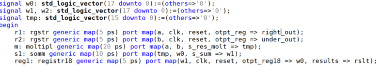
These three elements are implemented with a behavioural architecture while i am trying to implement the processing element with a structural architecture. I am really confused about how to assign the signals in order to send the output of the register as input of the sum.
These are some parts of my code.

Screenshot (109).png


Screenshot (110).png
 

I have no idea what you are showing here. Bits and pieces of I-dont-know-what.

Showing 3 lines of code is useless.

What is your specific problem?
 
Trivially, you connect the output port of one design entity with the input port of a another entity by associating both ports with the same signal. The signal act's as a connection wire.

I also suggest to avoid positional association and use named association for all ports. It makes the code readable and helps not to mix up ports.

By the way, why are you using structural style for basic functions that can be written in two lines of behavioral code (a reset and a clocked statement)? Is it an excercise?
 

I am sorry for my poor explanation of the problem, i'll try my best to rephrase it so, hopefully, it will be easier to understand my request.
My assignment is to implement a Sysyolic Array. This is composed of various blocks called processing elements which have the job to pass the two inputs they recieve to the elements on their right and under them, multiply their inputs, add them and store them thanks to a feedback register. Being "a" and "b" the inputs and being "c11" the first processing element, it has to implement the following equation: \[ c_{11}=\sum_{k=1}^3 a_{1k} * b_{k1} \]
The task requires that the multiplier, the feedback register and the adder are implemented using the behavioural architecture, meanwhile, every single processing element has to be built using the structural architecture.
My doubts hinge on how to connect, in the structural architecture, the output of the feedback register to the input of the sum. I guess the same signal has to be the output of the feedback register and the second input of the sum, that's what i am trying to do with the signal w0 and w1.
In my code i also added two initial registers just to pass the inputs to the next processing elements and a second output "results" of the feedback register which has to contain the results of the calculi going on inside the processing element.
I testbenched every components of the code and they work fine but, when i testbenched the whole processing element, the output "results" remains "0", making me think that the connection between the feedback register and the adder is wrong.
In the first attached picture i show how, in the struct architecture of the processing element, i linked the different components, while on the second one i show the architecture of the systolic array with the differents processing elements (to give a better idea of it, my task is to implement it just for 3x3 matrix, so it's easier than that).
I hope that this post sounds clearer than the last one, i am sorry but i am kinda new to the VHDL language.
I thanks everyone who have spent and are spending their time on this post, trying to solve my problems, i am grateful for it 🙂🙏
 

Attachments

  • Screenshot (112).png
    Screenshot (112).png
    88.7 KB · Views: 103
  • 3-s2.0-B9780127345307500088-f08-22-9780127345307.gif
    3-s2.0-B9780127345307500088-f08-22-9780127345307.gif
    13.6 KB · Views: 89

Status
Not open for further replies.

Similar threads

Part and Inventory Search

Welcome to EDABoard.com

Sponsor

Back
Top