Alan0354
Full Member level 4

- Joined
- Sep 6, 2011
- Messages
- 214
- Helped
- 30
- Reputation
- 60
- Reaction score
- 29
- Trophy points
- 1,308
- Activity points
- 2,709
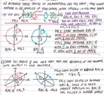
I have been trying to understand polarization match in the text from Balanis. The first attachment is the text scanned from the text explaining the polarization of an antenna in RECEIVING mode. I try to understand what the book said and I came up with my interpretation in my writing and drawings in the second attachment.
For point #2a in the text, I drew in Fig.1 to show two RHC antennas. The transmitting antenna is called RHC-A located at the origin and transmit at +z direction as shown. I show the E as rotating counter clockwise (CCW) as in Fig.2 where +z is coming out of the paper. The receiving antenna is called RHC-B and is located somewhere alone the z axis pointing back to the origin. The receiving antenna RHC-B being RHC, the direction of rotation is shown in Fig.3 as being rotating clockwise (CW) for obvious reason....because it is pointing at the origin alone the -z direction.
For #2b in the text, I use the same two antenna in Fig.1. The ellipse locus traced out by the E of the transmitting antenna RHC-A is shown in Fig.4 with TILT angle δ shown. The ellipse locus of the receiving antenna RHC-B is shown in Fig.5. The reason the ellipse is a MIRROR image of the transmitting antenna is because....again, the receiving antenna is pointing to the origin.
It is important in Fig.2, 3, 4 and 5, the z-axis is pointing out of the paper. Please tell me whether my interpretation is correct or not.

