Continue to Site

Welcome to EDAboard.com

Welcome to our site! EDAboard.com is an international Electronics Discussion Forum focused on EDA software, circuits, schematics, books, theory, papers, asic, pld, 8051, DSP, Network, RF, Analog Design, PCB, Service Manuals... and a whole lot more! To participate you need to register. Registration is free. Click here to register now.

[SOLVED] VCO Does not oscillate

Status
Not open for further replies.

Mahruz

Junior Member level 3
Joined
May 16, 2022
Messages
28
Helped
0
Reputation
0
Reaction score
0
Trophy points
1
Activity points
334
Hi All,
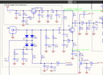
I am stuck in understanding why the below VCO circuit does not oscillate marked in red colour box.
I tried changing the transistor but, still, there is no oscillation.
For a good PCB; after testing and checking at C10 in a spectrum analyser; I roughly get -10dBm.

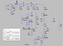
Is there a method to simulate the below circuit in AWR or LTspice or so ?
1667455586054.png


Thanks,
Mahruz
 

It can be simulated in ADS or AWR but components' specifications and especially CR's equivalent circuit should be supplied.
Coaxial Resonators don't work below 1GHz, and I guess that this oscillator has been designed for sub-GHz frequencies. There is a mistake meseems.
 

I agree with BigBoss but my concern is that Q3 has to be fully conductive before enough current can flow to start oscillation. The image is cut off on the right edge but my guess is the FET is a BS138 so it would need at least 2V on it's gate to ensure conduction and preferably would have a little more.

Brian.
 

Many oscillators will fail to start in simulation because there
is a stable DC solution.

Applying a "kick" to the circuit (a small current pulse at t=1n)
can do what, in the real world, thermal or electrical noise will.

Presuming, of course, that the circuit is any good.
 

Hi All,

Q2 datahseet is :

Q3 datasheet:
I agree with BigBoss but my concern is that Q3 has to be fully conductive before enough current can flow to start oscillation. The image is cut off on the right edge but my guess is the FET is a BS138 so it would need at least 2V on it's gate to ensure conduction and preferably would have a little more.

Brian.
Hi Brian,
I have update the drawing as below to provide a better understanding. I will check on Q3 today and see how it goes.

1667504884718.png

It can be simulated in ADS or AWR but components' specifications and especially CR's equivalent circuit should be supplied.
Coaxial Resonators don't work below 1GHz, and I guess that this oscillator has been designed for sub-GHz frequencies. There is a mistake meseems.

Hi Big Boss,
The frequency of operation for this circuit is at the 804 to 825 MHz range.
Datasheet is :


Is there anything else to check for to can cause this issue?

thanks,
 

Attachments

  • 1667504353972.png
    1667504353972.png
    148.4 KB · Views: 111

1. There are circuit details that I don't understand. If L4 isn't fitted, how is D50 biased?

2. What is the design state? Is the circuit newly designed and has never operated before? Or is it an existing product, but possibly defective?

3. To check the design, we would need complete specification, also resonator and varicap part numbers.

4. Why there are there multiple schematic copies, each which different part identifiers?
--- Updated ---

Regarding transistor bias, it would be easy to determine Q2 Vce and Ic.
--- Updated ---

For a good PCB; after testing and checking at C10 in a spectrum analyser; I roughly get -10dBm.
-10 dBm what? Noise? Or discrete frequencies? In the latter case, how do you say it's not oscillating?
 
Last edited:

The health of an oscillator also depends on load impedance as well as used components. So, you should consider an oscillator with its' peripheral elements, not only oscillator itself. Therefore, an oscillator has to be carefully examined with PCB EM simulation and realistic-preferably measured- models. Without knowing all these stuffs, it's very hard to say something. There are also many unknown/not modelled components around it. The PCB seems correct and appropriate, but this is not enough. Small fraction of stray capacitance or a serial undesired inductance may kill the oscillation.
If I were you, I would simplify the circuit (using equivalent impedance of the amplifier circuit). If you can, measure CR s-parameter (S11) on a proper PCB and obtain realistic models of the active and passive components.

Technical Note: Oscillators are sensitive and unpredictable circuits and examination of these circuits looks to dig a hole with a needle.
 
Replace the L12 100nH inductor with bigger value (e.g. 1uH) and the VCO will oscillate. But you have to pick-up the output signal from the emitter, not from the collector, as it is now.
Using LTspice I get steady oscillation arround 145 MHz, using the values and components in the picture attached. I don't know what coaxial resonator you chose, so I use a 100nH inductor instead.

Never use an inductor on the control line of the varicaps (L10 in your schematic), because its reactance varies with frequency. Use instead a high value resistor.

I see that this is a CW transmitter. It is a very bad idea to key the VCO stage, as you do now. Set the VCO in continous mode, and key Q6 or Q7, or both.
 

Attachments

  • Colpitts_VCO.jpg
    Colpitts_VCO.jpg
    514.2 KB · Views: 120
There are certainly several very valid design points raised but my understanding of the original question is that it does function but one particular board is dead and therefore has a fault not exhibited on other samples. It could be a marginality problem given the design is somewhat suspect from the outset but I think Mahruz is looking for fault finding help.

Brian.
 

1. There are circuit details that I don't understand. If L4 isn't fitted, how is D50 biased?

2. What is the design state? Is the circuit newly designed and has never operated before? Or is it an existing product, but possibly defective?

3. To check the design, we would need complete specification, also resonator and varicap part numbers.

4. Why there are there multiple schematic copies, each which different part identifiers?
--- Updated ---

Regarding transistor bias, it would be easy to determine Q2 Vce and Ic.
--- Updated ---


-10 dBm what? Noise? Or discrete frequencies? In the latter case, how do you say it's not oscillating?
Hi FvM,

In response to your questions;
1. These are the questions that I am not certain about. I am not sure if L4 should or should not be there.
From your experience, should L4 be soldered with 220nH?

2. The design has been working for 1 out of 10 PCB's. It has high failure rate and I am unable to determine what the reason is for it.

3. The datasheet, I shall provide soon.

4. The schematic copies are me just replicating the design on my laptop, it has not impact.

5. I shall provide the Inductor datasheet tomorrow.

Thanks for the help.
Mahruz
--- Updated ---

Replace the L12 100nH inductor with bigger value (e.g. 1uH) and the VCO will oscillate. But you have to pick-up the output signal from the emitter, not from the collector, as it is now.
Using LTspice I get steady oscillation arround 145 MHz, using the values and components in the picture attached. I don't know what coaxial resonator you chose, so I use a 100nH inductor instead.

Never use an inductor on the control line of the varicaps (L10 in your schematic), because its reactance varies with frequency. Use instead a high value resistor.

I see that this is a CW transmitter. It is a very bad idea to key the VCO stage, as you do now. Set the VCO in continous mode, and key Q6 or Q7, or both.
Hi Vfon,
Is it possible, if you can share your LT spice design files with me?

Thanks,
 
Last edited:

Hi All,
I was able to fix the problem, it was the coax resonator not being soldered properly onto the PCB. It looked good but was cold joints.

Thanks all,
Mahruz
 

Status
Not open for further replies.

Part and Inventory Search

Welcome to EDABoard.com

Sponsor

Back
Top