Continue to Site

Welcome to EDAboard.com

Welcome to our site! EDAboard.com is an international Electronics Discussion Forum focused on EDA software, circuits, schematics, books, theory, papers, asic, pld, 8051, DSP, Network, RF, Analog Design, PCB, Service Manuals... and a whole lot more! To participate you need to register. Registration is free. Click here to register now.

Varying Vcc Power Amplifier

Status
Not open for further replies.

rahdirs

Advanced Member level 1
Joined
May 22, 2013
Messages
424
Helped
93
Reputation
192
Reaction score
91
Trophy points
1,308
Location
Mordor
Activity points
4,492
Hi all,

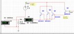
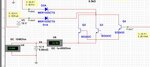
I designed a power amplifier shown in schematic 3(https://www.edaboard.com/threads/289823/#post1241393)that provides a current gain from 25 mA to 10 A keeping the voltage constant.The input to the power amplifier is an almost constant DC voltage between 11 & 12 V and at 15-25 mA. I need an output at same voltage and 10 A.

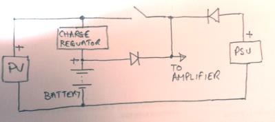
In that case the power amplifier was providing current by taking it from 18 V DC source.
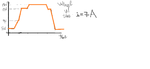
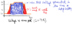
Now i have a source which gives constant current of 7 A but it's voltage varies as shown in figure 2.Can i use this source to provide current to power amplifier instead of 18 V DC source.

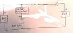
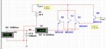
What i'm trying to say is like using that source to implement power amp as in the schematic 1 with ideal current source.It looks fine with current source but in my case voltage is also varying.
 

Attachments

  • Untitled.png
    Untitled.png
    16.2 KB · Views: 46
  • VaryingSource .JPG
    VaryingSource .JPG
    96.9 KB · Views: 46
  • Earlier Poweramp.JPG
    Earlier Poweramp.JPG
    91.6 KB · Views: 51
Last edited:

I'm completely confused as to what you are trying to achieve. Firstly, those are not class A or AB amplifiers, it is just a darlington configuration using three parallel output transistors which incidentally should have current sharing resistors. As the output VOLTAGE folows the input by two Vbe drops, I'm not sure why you expect it to give particular current gain. The output current depends upon the load and you are essentially trying to set the voltage across it. If what you are saying is the current into the load drops over time, the most likely reason is that one of Q2, Q3 or Q4 has heated up and it's Vbe has changed, sharing the current equally between them will help but but the end of the day, it's still just behaves like a single darlington pair.

Brian.
 

@betwixt:I never said that the configuration in the schematic is either class A/AB, in that other thread i wanted to design a class A/AB power amp but found that darlington configuration is good enough for me.

I need a current gain because,the input of the power amplifer comes from the op-amp which could only provide a max.of 30mA. But the stage next to power amp needs 10 A current,so i used darlington configuration & the current of (10 -0.03) A =9.97 A is provided from Vcc.
No transistor has heated up.
But i don't want my Vcc to provide 9.97 A.I need that source described in post #1 to provide current instead of Vcc.
 

Just to clarify this, are you asking for assistance in the design of a Voltage controlled Current source?

Should this be the case, then look in the Analog Devices (or other Semiconductor Manufacturers) datasheets which will give you the relevant information on how to use a Power Transistor, current sense resistor and Operational Amplifier to implement this

Mik
 

You never mentioned the other thread - I took this as being something new.

I'm still confused though, a VCC source is (by definition) a voltage source, are you asking for a constant current source? One that changes it's voltage in order to maintain the same current into the load. The current drawn has no realtionship to a fixed voltage unless the source cannot comply with demand.

Brian.
 

I'm still confused though, a VCC source is (by definition) a voltage source, are you asking for a constant current source? One that changes it's voltage in order to maintain the same current into the load. The current drawn has no realtionship to a fixed voltage unless the source cannot comply with demand.
@betwixt:
  • I think you understand the part that current the power amplifier is providing is coming from Vcc. Where do i get Vcc from,my power supply.So,i'm using current from my power supply.
  • Why am i using this power amplifier,why do i want a current gain:I want to charge a battery,i'll take of charge controller & that stuff but i generally need current around 10-20A,so i used the darlington configuration to provide the remaining current.
  • I don't want my power supply to provide this current.I should've told this in post#1 but i want a solar panel to provide this current.The solar panel I-V curve for a constant load shows that it's current remains constant.
  • So i want my panel to give this current to the power-amplifier.But i can't directly connect panel to collector of transistor even if it can provide 7-10A current,because it voltage randomly varies as in figure in post #1.

Capture.JPG
 

Still a bit confuddled...

Do you mean you have two power sources, one is your power supply (I assume powered from AC mains) and one is a solar PV system. You want to charge a battery from the PV and if it's voltage is high enough, use it to power your amplifier, otherwise use the power supply.

It sounds like what you need is two Schottky power diodes, one from the power supply and one from the battery, both feeding the amplifier and a charge regulator between the PV and battery to prevent overcharging.

Am I on the right track?

Brian.
 

Do you mean you have two power sources, one is your power supply (I assume powered from AC mains) and one is a solar PV system.You want to charge a battery from the PV and if it's voltage is high enough, use it to power your amplifier, otherwise use the power supply.
It sounds like what you need is two Schottky power diodes, one from the power supply and one from the battery, both feeding the amplifier
@betwixt:Yes,i have two power sources,one is my power supply(obtained from 220V AC) & other is solar panel.I did until the part where you use solar panel to charge battery when it is generating high voltage & use power supply when panel is down to charge battery and many systems which implement this are available in market.

  • But,i wanted to a bit more.I attached an image(looks crappy,"had to do it in paint")which explains what i want to do. Using the panel to charge battery is when it is generating high voltage i.e. using power generated in blue region.
  • What i want to do is also use the power that it generates in the red region(by taking help of power supply from AC mains),where it is generating some power,but the voltage isn't sufficient to charge the battery.
  • The power that the solar panel generates in the red region is significant(because on many cloudy days,it generates this) but un-usable because you can't charge the same 12 V battery at 5 V/7 V.I want to use this power,add a little power from AC mains and supply it to the battery.In the end,i manage to save some power.

Let me take an example,say i need to charge 12 V battery of 150Ah Capacity.I need to give a charging current of 10 A at 14.5 V to charge it.So instantaneous power required = 14.5 V * 10 A = 145 W.During peak of panel,solar panel supplies this 145 W.At night,when panel doesn't give any o/p the mains(220 W) supplies this 145 W.
At evening time/at morning when panel generates some voltage less than 12 V,say 6 V,it isn't usable to charge battery.But it is generating 6*10 = 60 W power.I want to use this power by supplying 85 W power from AC supply. 60W + 85W =145W.
Am i clear ????
 

Attachments

  • Untitled.png
    Untitled.png
    49.9 KB · Views: 38
Last edited:

OK, I understand but I think you will run into problems. The first is that the PV will produce almost full voltage even in partial sunlight so you cannot assume to measure it's voltage to control your system. What happens is the voltage it produces will drop under load more when the light is dimmer. Without a load your 'change over' will not work.

The second problem is in deciding where the current is to be diverted, if you feed it to the battery it will drop the voltage to your amplifier and vice versa so you cannot easily choose how to share it.
My sketch shows a possible way to do it, the switch would be closed when the voltage across the battery reached about 14V.

3444068000_1370506211.jpg


To make it more efficient you would have to use MPPT technology and probably a step-up inverter, both of which are quite complicated. To be honest, a PV connected straight across the battery and a pair of Schotky diodes feedng the battery and PSU to your amplifier would probably work just as well. You would not be wasting power because the PSU would only be providing 'top up' current anyway and this would decrease as the battery/PV charged and became the dominant power source.

Brian.
 

@betwixt: Ok,i'll look into it.
I want to you to comment on my approach.It's not complete,but here it is. I used two op-amps,one as a subtractor & other as adder.
  • The subtractor gives at it's output how much the panel voltage falls short from 15 V.I add this difference by using adder to panel voltage to get 15 V.
  • Now,as op-amp max.output current is 30 mA,i used a darlington configuration to amplify current.
  • As we know the current must come from collector node to provide current gain.I wanted to bring the current needed for current gain from current produced by panel.Do you think i could do this??
 

Attachments

  • Capture.JPG
    Capture.JPG
    102.9 KB · Views: 46
Last edited:

The second problem is in deciding where the current is to be diverted, if you feed it to the battery it will drop the voltage to your amplifier and vice versa so you cannot easily choose how to share it.
My sketch shows a possible way to do it, the switch would be closed when the voltage across the battery reached about 14V.
3444068000_1370506211.jpg
@betwixt:No,i am not trying to do what your sketch says.The sketch attached shows what i want to do.

What i want to do: PV rating (15 V,7A),Battery to be charged(12V,150Ah,sfe charging current:10 A.Power inst.supp to battery = 14*10=140 W),mains:(15V)
The switch opens only when PV is giving out 14 V.
If PV is giving voltage at 3-12 V,the switch would be closed.The PV gives (3 - 12) V* 7 A = 21 W - 84 W.The mains should supply 119 W - 56 W.3444068000_1370506211.jpg
 

Attachments

  • 3444068000_1370506211.jpg
    3444068000_1370506211.jpg
    21.4 KB · Views: 37

I still think you are looking at it wrongly - I DO understand what you are trying to do but PV doesn't work like that. When the PV is only producing low voltage, it will also only produce low current. The open-circuit voltage of a PV will go to maximum even under poor light conditions but under even a small load will drop to almost nothing. You can't recover enough power from an under insolated PV to make it worthwhile trying. The only way you will maximize the power is to use an MPPT system followed by an inverter to give you steady voltage. You seem to think that 145W at 12V from the PV means you will get half that 72.5W when it is only producing 6V. Even if Ohms law agreed with you, the physics of PV generation wouldn't!

Brian.
 

@betwixt: Ok,so my earlier assumption that panel generates half it's peak power at 6V seems false.I was misled by blogs on panels found on net which showed that solar panel is a kind of constant current source as in figure.Can you suggest some resources where i can find quality information on physics of PVs.
 

Attachments

  • Capture.JPG
    Capture.JPG
    22.7 KB · Views: 41

The graph demonstrates the maximum power point not the voltage under different illumination. This is the point I mentioned earlier when I suggested an MPPT system. MPPT (Maximum Power Point Tracking) extends the output of a PV by controlling the current drawn from it and using it to boost the output voltage. It gives a few percent more output when the PV is starting to lose output power. Unfortunately, the maximum power point isn't very well defined and varies from one PV to another, that's why a MPPT system uses analytical techniques to find the optimum point. Rather than looking at individual PV specifications, research MPPT for a better understanding.

Brian.
 

Status
Not open for further replies.

Similar threads

Part and Inventory Search

Welcome to EDABoard.com

Sponsor

Back
Top