Continue to Site

Welcome to EDAboard.com

Welcome to our site! EDAboard.com is an international Electronics Discussion Forum focused on EDA software, circuits, schematics, books, theory, papers, asic, pld, 8051, DSP, Network, RF, Analog Design, PCB, Service Manuals... and a whole lot more! To participate you need to register. Registration is free. Click here to register now.

Varistor(MOV)calculation

Status
Not open for further replies.

xchcui

Member level 2
Joined
Mar 14, 2016
Messages
50
Helped
0
Reputation
0
Reaction score
2
Trophy points
8
Activity points
485
Hi.

When we connect a resistor in series with an LED to a DC voltage source, in order to determine the resistor value, we subtract the voltage drop of the LED from the voltage source and the result we divide by the current that we want to flow in the circuit.
If we change the resistor value, the current will decrease or increase, but the voltage drop on the LED will remain the same.
If I connect a varistor (MOV) in series with a resistor to a voltage source and change the resistor value,will the voltage drop on the varistor stay the same?


For example: If I connect to 500VDC source to a MOV-14D431R in series with a 70kΩ resistor (see picture,) the voltage drop on the varistor will be 430V (rated voltage,) the voltage drop on the resistor will be 70V, and the current will be 1mA, which fits the specifications.

What will be the voltage-drop on the MOV and on the resistor if i will change the resistor to 1.5MΩ?Will the voltage-drop on the MOV will still be 430V?
I attached a U-I graph that include the MOV-14D431R.

Thanks

varistor  calculation.png

.
 

Hi,

first of all:
every device comes with a datasheet. Usally there you can find the relation between voltage and current.

All currents in a series connection is the same.
All voltages in a sereis connection are added and give in total the input voltage.

MOV: Many of them are "protection devices" and not meant for steady current. They are meant for short extremely high peak currents. Read the datasheet thoroughly.

Neither the voltage across a LED nor across a MOV is independent of current. All devices will have differnt voltage at different current. But the relation differs a lot. For "over the thumb" calculations you may say that the voltage of a LED is almost constant for a given current range. Fore precise calculations this never is true.

Don´t forget that the V-I relation depends on
* device type
* production batch
* age
* temperature
* and more...

If you can´t calculate the voltages and currents by hand
* you may do it graphically
* or use one of the circuit simulation tools

Klaus
 

every device comes with a datasheet. Usally there you can find the relation between voltage and current.
Hi,klausST.
Yes,i attached the U-I graph from the datasheet in my question of the 14D431K MOV.
Neither the voltage across a LED nor across a MOV is independent of current

This sentence looks like a sentence from Psychometric test:)
You meant that the voltage across the led and across the MOV is depended on the current,right?

So if the 1.5MΩ resistor(on the right circuit)will reduce the current to a certain value, the voltage drop across the MOV must match the current on the graph,more or less(since there is a minimum and maximum values for MOV).

For example,i can't assume(right circuit)that the voltage drop across the varistor is 430V with the 1.5MΩ resistor in series and do this math:
500V-430V(mov)=70V(R2),70V/1.5MΩ=46uA,since the 46uA is not match to 430V(MOV)in the graph.

But this math is the right one:
500V-300V(mov)=200V(R2),200V/46uA=4.4MΩ,since the 46uA is match to
the 300V drop across the MOV according to the following graph.Am i right?


VARISTOR U-I1.jpg
 
Last edited:

Hi,

a MOV is designed to clamp voltage. This is it´s job.
"Maximum voltage" also means maximum resistance.

Leakage current is something that you don´t want. it´s like an error.
I´d not rely on the leakage current in the meaning of "typical wanted current".
The datasheet gives "maximum current" which also means minimum resistance.

Klaus
 

Looking at the curve slope I see A 10V rise rise from 1 to 10 mA , so
that’s equivalent to about 1 kohm which is insignificant compared to a large change in Rs so you can assume Vf on the MOV does not change much in that current range. But then the plot is nominal with some tolerance.

1ma is where the curve is flattest so perhaps when using the correct fixed R the tolerance is lowest.
 
Last edited:

Looking at the curve slope I see A 10V rise rise from 1 to 10 mA
Hi Tony.

Isn't the curve slop(14D431R)that rise from 1mA-10mA: 60V rise (480V to 540V)?

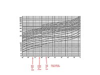
One more thing about the U-I graphs of the varistors.

When the varistor graph is drawn as you may see at my attached photo,

Do the horizontal lines between the round numbers(marks with arrows at my photo)indicate 1 unit or 5 units?I think it indicate 5 units,but i would like to verify this.

varistor u-i1.jpg
 

Horrible diagram. Won't even try to guess about axis scaling.
A recent datasheet of your MOV is here https://www.bourns.com/docs/Product-Datasheets/MOV14D.pdf

Here's the respective V/I curve for 14D431K (topmost line). You should however consider two points.
1. As explained by KlausST, it's a limit curve, on left side minimal voltage for a specific current, not nominal.
2. Apparently the line isn't drawn very accurately, you get different slope in different document versions. Respectively I doubt that it's suited to find an exact operation point.

1666001395566.png

Generally, you are solving the nonlinear equation I*Rser + Vmov(I) = Vb. If you don't have a function for Vmov(I), you can find the operation point iteratively in the V/I diagram. You can also refer to a SPICE simulation model provided by Bourns https://www.bourns.com/engineering/MOV14D/MOV_14D431K.LIB

But it's specifying the V/I curve only very roughly in 1:10 current steps
Code:
G1 N001 Vout TABLE {V(VG1,0)}=
+(193.5,1.E-6) (292.4,1.E-5) (356.9,1.E-4) (430.0,1.E-3)
+(473.0,1.E-2) (494.5,0.1) (516.0,1) (559.0,10) (774.0,100)
+(1290,1000) (2580,10000) (20000,5.E+5)

Interpolating the table by polynomial (e.g. using MS Excel) would give you the best available fit.
 

Thanks for the information fVm.
About the horrible diagram that you mentioned.
I know that it is very blurred and i wasn't meant
that someone will use it for any calculation.
I would like to know what the horizontal line in between indicates.
So i attached it for an example to my question.
When there are 8 horizontal lines between
for example:10^-3A(1mA) to 10^-2A(10mA),i know
that each horizontal line(of the 8)indicates 1mA difference.(1mA,2mA......,9mA,10mA).
But what if there is only 1 horizontal line between(1mA to 10mA):
10^3 to 10^2?does this 1 line indicate:
2mA(1mA,2mA,10mA)?
5mA(1mA,5mA,10mA)?
or 9mA?(1mA,9mA,10mA)?

varistor u-i1.jpg
 

Hi,

these are vertical lines and mean "5 units"

Klaus
Oops,my mistake.So yes,I meant vertical.(y)
Thanks for clarify this detail.
I see that this line indicates half of the value
between two main vertical lines.(1mA,5mA,10mA).
Thanks to everyone for your help.:)
 

3 is about middle on all log displays so 5 is right of centre
--- Updated ---

Hi Tony.

Isn't the curve slop(14D431R)that rise from 1mA-10mA: 60V rise (480V to 540V)?

One more thing about the U-I graphs of the varistors.

When the varistor graph is drawn as you may see at my attached photo,

Do the horizontal lines between the round numbers(marks with arrows at my photo)indicate 1 unit or 5 units?I think it indicate 5 units,but i would like to verify this.

View attachment 179152
Yes but 10-1=9 using a decade log scale, pick the same plot to see my choice
--- Updated ---

Horrible diagram. Won't even try to guess about axis scaling.
A recent datasheet of your MOV is here https://www.bourns.com/docs/Product-Datasheets/MOV14D.pdf

Here's the respective V/I curve for 14D431K (topmost line). You should however consider two points.
1. As explained by KlausST, it's a limit curve, on left side minimal voltage for a specific current, not nominal.
2. Apparently the line isn't drawn very accurately, you get different slope in different document versions. Respectively I doubt that it's suited to find an exact operation point.

View attachment 179155
Generally, you are solving the nonlinear equation I*Rser + Vmov(I) = Vb. If you don't have a function for Vmov(I), you can find the operation point iteratively in the V/I diagram. You can also refer to a SPICE simulation model provided by Bourns https://www.bourns.com/engineering/MOV14D/MOV_14D431K.LIB

But it's specifying the V/I curve only very roughly in 1:10 current steps
Code:
G1 N001 Vout TABLE {V(VG1,0)}=
+(193.5,1.E-6) (292.4,1.E-5) (356.9,1.E-4) (430.0,1.E-3)
+(473.0,1.E-2) (494.5,0.1) (516.0,1) (559.0,10) (774.0,100)
+(1290,1000) (2580,10000) (20000,5.E+5)

Interpolating the table by polynomial (e.g. using MS Excel) would give you the best available fit.
This graph is sharper but not significantly better. My observation is the drop in voltage below 1mA due to DC test and above 1mA for impulse test 1| 10 us. Perhaps from inductive voltage
 
Last edited:

This graph is sharper but not significantly better.
The basic misunderstanding is to read the max leakage and max clamping voltage limit lines as accurate I/V characteristic specification, but they neither are nor claim to be. As KlausST stated, MOV is designed to clamp surges, not as a voltage regulator.
 

The basic misunderstanding is to read the max leakage and max clamping voltage limit lines as accurate I/V characteristic specification, but they neither are nor claim to be. As KlausST stated, MOV is designed to clamp surges, not as a voltage regulator.
Agreed. It could act as a crude voltage reference <= 1mA but self heating and tolerances could be large but ESR will be minimized at 1mA
 

Hi,

heating is about half a Watt per milliampere. It will heat.

I don´t see why ESR should be minimized,

I see it this way:
Leakage current is some kind of unwanted error. The manufacturer gives a maximum limit of a value that is guaranteed to be lower. How much lower depends on a lot of things. I guess even the purity of the silicon. So it may vary a lot from batch to batch. Even from part to part. I would not be surprised if I measure it to be just 1% of the given maximum value.

Klaus
The ESR always reduces with quadratic semi’s in rising current until the linear bulk Rs dominates . So above 1mA the test rises in R due intolerance to heat using the impulse test. You could certainly use less current and heat and the tolerances might be 10% like Zeners. Some may experiment to verify my hunch.
 

Status
Not open for further replies.

Similar threads

Part and Inventory Search

Welcome to EDABoard.com

Sponsor

Back
Top