Continue to Site

Welcome to EDAboard.com

Welcome to our site! EDAboard.com is an international Electronics Discussion Forum focused on EDA software, circuits, schematics, books, theory, papers, asic, pld, 8051, DSP, Network, RF, Analog Design, PCB, Service Manuals... and a whole lot more! To participate you need to register. Registration is free. Click here to register now.

LED calculation

Status
Not open for further replies.

Rajinder1268

Full Member level 3
Joined
Mar 20, 2021
Messages
162
Helped
1
Reputation
2
Reaction score
4
Trophy points
18
Activity points
1,228
Hi,
I am driving a blue LED from a PIC GPIO.
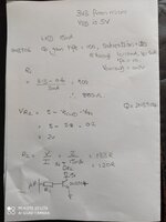
The transistor is 2N3904, LED is worth elektonik 151033bs0300. The supply for the LED is 5V, I am driving it at 15mA.

I have attached my calculations. Do they look correct?
Do I need a pull down at the base of Q1 to ensure the transistor is off and we don't get the LED to light on switch on.

Thanks
 

Attachments

  • IMG_20220708_111403.jpg
    IMG_20220708_111403.jpg
    1.4 MB · Views: 134

Hi,

(a 1500 kBytes photo is overkill for that small information it gives. A 20kByte photo should work, or 1kByte as text, or a couple kBytes as screenshot from a formula editor)

I see nothing really "wrong".

--> Good thing: I guess it will work.

But I still see some issues:
* why do you say 3.3V from microcontroller while VDD = 5V. I expect higher output. Please refer to microcontroller datasheet V_OH vs I_OH diagram.

* where do the "3mA" at the calculation for R1 come from? Nothing wrong with 3mA, but 1.5mA should be sufficient.

You calculate with typical (optimal) values. Maybe you also want to do worst case calculation, too.

Like minimum LED current with
* minimum microcontroller supply
* minimum microcontoller V_OH
* maximum saturation voltage of BJT
* low BJT temperature for high V_BE
* minimum LED powersupply voltage
* maxmum LED V_f
* maximum resistor tolerance
.. to see if you get the brightness you expect

or the other worst case for high LED current ... and power dissipation of each device.

If you never done this, then I recommend to do this, just to get a feel for the extreme values.
Mind: the lower the typical voltage cross R2, the more critical are min and max worst case values.
(with 2V you are rather safe)

Klaus
The micro is powered from 3V but I have a 5V, so used that to power the LED as it has a higher forward voltage drop around 2.8V. I will try with minimum values as you suggest, it will be a good exercise.

Do you think a pull down is required, sorry for the size of the image.
 

Yes on pulldown, basically use 10K, to absorb leakage when processor output
in hi z when it starts up. Modern LEDs can emit at very low currents, so want
off until processor takes control.


Regards, Dana.
 

Hi,

Pendantically:
Again: if the microcontroller is supplied with 3V you can't expect 3.3V at the output.
You always get less at the output than the supply voltage. How much less: see the datasheet. There may be big variation between different devices.

Pull down: Where?
Across B-E: not needed as long as the microcontroller V_OL is low enough. (usually it is)
Across the LED (to ensure it is really OFF). May be useful if the leakage current of the BJT is too high.
(only valid for dedicated precision measurement circuits)

Klaus
 

Yes on pulldown, basically use 10K, to absorb leakage when processor output
in hi z when it starts up. Modern LEDs can emit at very low currents, so want
off until processor takes control.


Regards, Dana.
Thanks, will this not form a voltage divider with R1? Is that going to cause any issues?
 

Yes, you lose a little drive but as long as you meet the rule of thumb Ib = Ic / 10,
normally called forced beta, to insure transistor is in saturation you are good to go.

And value of base R to gnd has to absorb leakage and not turn on transistor, while
being low enough to not make base susceptible to noise pickup.


Regards, Dana.
 

Hi,

to add what Dana wrote..

When ON the pull down resistor acts like a "constant" current that is subtracted from the base current.
The voltage is about constant at 0.6V and the resistance is 10k, then the current "missing at the base" is just 0.6V/10k = 60uA.
You should have about 1.5mA base current (still including safety margin) and you have about 3mA. More accurately: 3mA - 60uA = 2.94mA. Very uncritical.

And yes, for base voltages 0..0.5V (OFF) it acts like a voltage divider.
0.5V also means 50uA ... so it´s safe for some leakage and noise currents up to 50uA not to accidentally switch ON the BJT.
That´s the main idea behind this pull down.

Klaus
 

Status
Not open for further replies.

Similar threads

Part and Inventory Search

Welcome to EDABoard.com

Sponsor

Back
Top